
Specifications


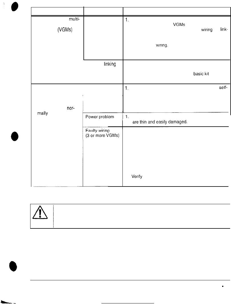
LINKING PROBLEM TROUBLESHOOTING
Symptom Cause Required Action
l Cannot connect multi-
Faulty wiring
1.
Install required crossover between cabinets. Each
ple Video Game
coupler connects two VGMs (one pair). Do not use
Machines (VGMs) standard telephone type couplers or wiring for
link-
together
ing.
2. Use only 10 Base-T, Ethernet-type. Category 5.
twisted-pair wiring.
3. Do not overextend linking cables supplied with
VGM.
Improper llnking
hardware
1.
Use required network hub for your local network.
A Hub Link Kit permits up to four VGM connec-
tions. Array completion requires basic
kit
brackets
and spacers.
l VGM does not recog-
Improper settings
1.
Record any error messages that occur during
self-
nize other players in
test.
linking operation ~
2.
Check that each VGM has a unique ID number.
3.
Access the Diagnostic menu, then select LINKING
l VGM functions nor- TEST. Confirm the link is enabled.
mally
by itself
Verify the hub receives power. AC adapter wires
1. Inspect hub Indicator lights.
l Illuminated indicator lights for each active port
light up if the cable(s) are properly connected.
l Check for cable continuity from hub to VGM for
L
each indicator that failed to light.
2.
Assure no loose wires are caught in hinges, doors
or under cabinet.
3. Verify linking cable connects to CPU Board for
each game.
4.
Verify
each linking cable operates properly by
placing it in a working game.
L
CAUTION
Do not remove or install any connector when the power is turned on. Installation under power
will damage the circuit boards, ROM’s or hard disk drive and void the warranty.
ARCTIC THUNDER
TROUBLESHOOTING
-
5