
Specifications


CHAPTER 5 WIRING
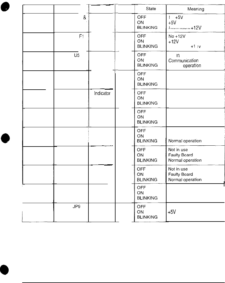
SUBSTITUTE BOARD LED INDICATOR STATUS TABLE
I
c
~-
Function
Indicator
--
Indicator
No +5V
+5V Present
Intermittent +12V
+f2V Present
intermittent +I 2V
d
Not
In
use
Cammumcation error
Normal operation
Not in use
EEPROM Not Responding !
Normal operation
Not in use
I
Security error
Normal operation
Not in use
Board reset
Normal operation
Faulty Board
Faulty Board
Not in use
/
Faulty Board
!
Normal operation
No power
+5V present
Intermittent power
Location ColorDesignation
Red
Near fuse F2
&
JP15 connector
Near fuse Fl
D 28
D 25
Red
Red
D 24 Near
U5
Indicator
D 23 Near U5
Indicator
-__-
Indicator
Red
D 22
Near U5
Red
Red
Near U5 Indicator
D 21
D 17
Indicator
__-
Indicator
__-
Indicator
Green
Green
Near U5
Near U5D 18
Green
D 14
Near U5
D 20
Near U5 Indicator Green
D 26
Near JP9 Indicator
Red
ARCTIC THUNDER
5