
Installation Manual
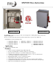

MNPVHV Disco Instructions (continued)
8 | P a g e 1 0 - 065- 1 R E V : F
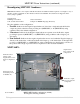
Reconfiguring MNPVHV Combiners continued: MNPV16HV
The following instructions assume starting from the default (parallel) configuration. If starting from another
setup then either revert to the default (Parallel) configuration or follow the instructions for the desired
configuration bearing in mind that the instructions may ask you to add/remove a busbar or label that has already
been added/removed. If reverting back to parallel follow the instructions for the current configuration in reverse.
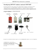
Components supplied for reconfiguring MNPV16HV:
See page 31 for quantities.
3-321 Busbar
6-093-1 3/8-16 Kepnut
9-458-1 Strain Relief
The parts above (included) are all that is required to convert the MNPV16HV Combiner to any of its configurations.
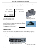
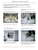
On TYPE 4X units a special sealing
screw is used to ensure that the unit is
water-tight. Use of other screw types
will compromise the seal and should
not be used.
9-298-1 Box Lug
5-124-2 White
Insulating Block
5-124-3 Red
Insulating Block
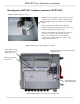
5-118-1 ¾” to ½” Adaptor
5-126-1 Gasket
5-119-1 Nut
5-146-1 Hole Plug
5-149-1 Washer
5-147-1 Nut