
Installation Manual

MNPVHV Disco Instructions (continued)
4 | P a g e 1 0 - 065- 1 R E V : F
Introduction
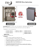
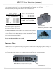
The MNPVHV series of combiners are designed for indoor / outdoor use. Type 4X have been tested to be
watertight to 2 meters underwater, so they are sure to be watertight above sea level. The MNPV4HV and
MNPV6HV are basic disconnecting combiners while the MNPV8HV and MNPV16HV are reconfigurable to
accommodate Non-Isolated inverters or to divide one combiner into two separate halves to power 2 inverters.
Overview of size/ratings:
MNPVHV4 TYPE 3R ---- 4 position, 80A, NEMA 3R
MNPVHV6 TYPE 4X ---- 6 position, 100A, NEMA 4X
MNPVHV8 TYPE 3R 8 position, 100/200A, NEMA 3R or 4X, configurable as
MNPVHV8 TYPE 4X 4 plus and 4 minus positions for non-isolated inverters
MNPVHV16 TYPE 4X ---- 16 position, 200A, NEMA 4X, configurable as
8 plus and 8 minus position for non-isolated inverters
MNPVHV8-DLTL ---- 4 plus and 4 minus position for non-isolated inverters NEMA 4X
4 plus and 4 minus position for non-isolated inverters NEMA 3R
MNPVHV16-DLTL ---- 8 plus and 8 minus position for non-isolated inverters NEMA 4X
8 plus and 8 minus position for non-isolated inverters NEMA 3R
Installation
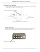
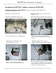
To remove the deadfront:
Note: The plastic dead front fits very tight. You must first remove the lid in order to
remove the deadfront.
On MNPV4HV units, pry off the lid as shown using something like a
screwdriver as a lever. The dead front then lifts out easily.
On TYPE 4X units the deadfront is secured to the busbars just above the
fuseholders. To remove it, gently lift it out from the top.
To reinstall the deadfront on all units, press it gently into place. There will
be a gentle snap when it seats.
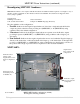
The installation of a PV combiner is fairly straight forward. Select the location to install your combiner first. Some systems
have the PV modules located close to the inverters. If this is the case, you can elect to mount the MNPV inside and run each
PV string down to the MNPV inside the building. This is convenient for trouble shooting and upgrading. For longer runs the
combiner will be mounted outdoors on the pole for pole mounted PV arrays or similar mounting for rack mounted arrays.
Combiners with a TYPE 3R enclosure can be mounted in the vertical position or slanted backwards to accommodate up to a
3/12 (14°) roof pitch. All unused holes should be blocked using RTV sealant or something similar in order to keep rain and
insects out of the enclosure. Care must be taken to insure that no water will get on terminal busbars or fuse holders when
mounted less than vertical. Type 4X units are submersible to two meters in any orientation, so it will certainly be watertight
above sea level. Be sure to comply with all local and national code requirements including National Electrical Code,
ANSI/NFPA 70. Use Class 1 wiring methods for field wiring connections to terminals of a Class 2 circuit. Use only 14-1/0
gauge AWM wire. Select the wire gauge used based on the protection provided by the circuit breakers/fuses. Combiners
should be mounted with #10 or larger stainless steel hardware.
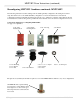
There are various wiring diagrams and system examples available at www.midnitesolar.com click on Documents at the top
of the page for links to wiring diagrams in PDF as well as links to AutoCad wiring diagrams and even solid models aimed at
aiding the system installer and designer. As such we request that they not be used for any other purpose.
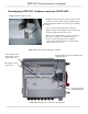
Remove top cover prior to removing
the deadfront on Type 3R units.