
Installation Manual

MNPVHV Disco Instructions (continued)
18 | P a g e 1 0 - 065- 1 R E V : F
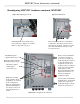
Installing MNSPD:
The MNPVHV Combiner comes with 1 MNSPD to protect against surges. A second MNSPD
(sold separately) can be added to protect 2 inverter configurations. Refer to the wiring diagrams starting on
page 17.
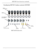
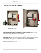
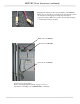
MNSPD Surge Protector Device
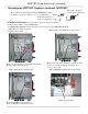
Remove the hole plug from the side of
the combiner. Remove the nut from the
MNSPD. Pull the wires through the side
of the combiner and secure with the
supplied nut. Insure that the silicone
washer is installed on the outside of the
chassis to maintain watertightness.
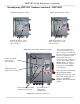
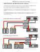
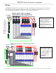
The wiring varies based on which configuration is used,
so the wires will need to be cut to length. Refer to the
wiring diagrams beginning on page 17 for details on
your configuration
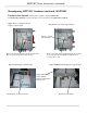
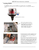
In this example (2 Inverters) the Black wire is run to the
Negative and cut to length, stripped and secured in in the
Negative busbar. Add a length of white heatshrink to the
end of this wire to signify the grounded conductor. The
red connects to the combined PV Plus busbar, the green
wire goes to the ground terminal block. The second
MNSPD (sold separately) connects in the same way to the
other PV Positive and Negative busbars with the green
connected to the ground terminal block.