
Installation Manual

MNPVHV Disco Instructions (continued)
12 | P a g e 1 0 - 065- 1 R E V : F
Reconfiguring MNPVHV Combiners continued: MNPV8HV
Parallel to 2 Inverters: See page 6 for a definition of each configuration.
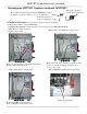
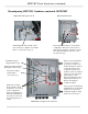
Starting with a parallel configured MNPV8HV.
The MNPV8HV TYPE 4X is shown, but the process is the same for the MNPV8HV TYPE 3R.
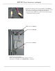
Remove Positive and Negative terminal blocks and the
Negative jumper busbar as shown.
Step 1: Remove Output blocks and
Negative jumper busbar
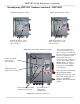
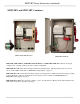
Remove Positive jumper busbar from switch, set aside,
it is not used in this configuration. Replace nut on
lowest position only.
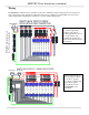
Step 2: Remove Parallel Positive Output busbar
Install Supplied PV Positive busbar for 2
inverter configuration. Oriented as shown.
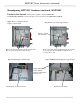
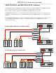
Step 3: Install Positive Output busbar
Busbar shown installed
Step 3 continued: Install Positive Output busbar
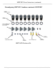
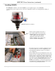
These additional busbars supplied with the MNPV8HV Combiner
are all that is needed to convert it to any of its configurations
PV Positive busbar for 2
Inverter configuration
PV Negative busbar for
Non-Isolated configuration