
MNPSB Instructions


MNBN Installation Instructions (continued)
6 | P a g e 1 0 - 2 19- 1
R E V : -
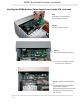
Installing the MNBN BirdNest Power Supply Power Supply PCB: Continued
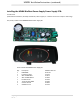
Step 7: Strip one end on the red and
white wires included in the kit ¼” and
connect them as shown with the red
wire on the left side of the terminal
block marked “PV+” and the white
wire on the right side marked “PV-“.
Route the wires downward under the
large switch.
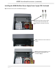
Step 8:
Installing the included MNSPD Surge protector with the MNBN.
First, select the mounting location for the MNSPD. There are several knockouts located on the sides and
bottom that can be used for this. Remove the desired knockout, pull the MNSPD wires through and
secure with the supplied nut.
MNSPD Shown installed in left side knockout.
Crimp one of the small red terminals on the red wire from the circuit board terminal block. Be sure to
make a strong secure connection. The purpose of this terminal is to allow the 18 AWG wire to be held
securely into the terminal strip.
The white wire from the circuit board terminal block may be crimped into the yellow terminal along with
the black wire from the MNSPD or it may be crimped by itself into the second red terminal.