
MNEDC Breaker Specifications


60 Johnson Avenue • Plainville, CT 06062–1177 • Phone: (860) 793–9281 • Fax: (860) 793–9231
Email: sales@carlingtech.com • www.carlingtech.com
60 Johnson Avenue • Plainville, CT 06062–1177 • Phone: (860) 793–9281 • Fax: (860) 793–9231
Email: sales@carlingtech.com • www.carlingtech.com
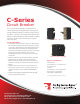
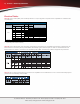
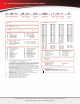
C-Series Handle UL Recognized – Ordering Scheme
|
7
— — — ——
1
Series
2
Actuator
3
Poles
5
Aux/Alarm
Switch
6
Frequency
& Delay
7
Current Rating
8
Terminal
9
Actuator
Color
10
Mounting
Bezel/Barrier
11
Agency
Approval
4
Circuit
Notes:
1
2
3
4
5
6
7
8
9
10
11
12
13
14
15
16
17
18
Actuator Code:
A: Handle tie pin spacer(s) and retainers provided assembled with multi-pole units.
B: Handle location as viewed from front of breaker:
2 pole - left pole 3 pole - center pole 4 pole - two handles at center poles
5 pole - three handles at center poles 6 pole - four handles at center poles
S: Handle moves to mid-position only upon electrical trip of the breaker. Available with
circuit codes B, C, D, E, F, G, H and K.
T: Handle moves to mid-position and alarm switch activates only upon electrical trip of
the breaker. Available with circuit codes B & C.
Standard multipole units have all poles identical except when specifying auxilary switch
and/or mixed poles. 4 pole max w/VDE. 5th pole available as Series Trip w/Voltage Coil only.
Switch Only circuits, rated up to 50 amps and 6 poles, and only available with VDE Certi-
cation when tied to a protected pole (Circuit Code B, C, D or H.). For .02 to 30 amps,
select Current Code 630. For 35 - 50 amps, select Current Code 650. For 55-70 amps,
select Current Code 670. For 75-100 amps, select Current Code 810.
Circuit Codes D,E,F,G,H & K available with Terminal Codes 1,2,4 & 5 only. Circuit Codes
D, F, H & K available up to 50 amps maximum Current Rating.
Consult factory for available Dual Coil options, as special catalog number is required.
Dual Coil Voltage Coils with Shunt Trip Construction trip instantaneously on line voltage.
Dual Coil Voltage Coils require 30VA minimum power to trip instantaneously and are
rated for intermittent duty only.
ers, one aux. switch is supplied, mounted in the extreme right pole.
Voltage coils not rated for continuous duty. Available only with delay codes 10 and 20.
Available with Circuit Codes B & D only, and up to 50 amps maximum.
Current Ratings 60 - 70 are available up to four poles maximum. Ratings 71 - 100 are
available up to two poles maximum.
Terminal Code 1 available to 60 amps maximum.
Terminal Codes 2,4,5 and C available to 50 amps maximum.
Terminal Codes 3,6 & 9 available to 100 amps maximum.
Terminal Code 7 available to 25 amps maximum.
Terminal Code A available to 100 amps maximum.
Terminal Codes 7,8,9 & C are not VDE approved.
No marking available. Consult factory. VDE/TUV Approval requires dual (I-O, ON-OFF)
or I-O markings on all handles.
Single pole only.
VDE/TUV: 30 amps max.; UL/CSA: 50 amps max.; Available in 2 - 4 poles only and
limited to AC Delays. “General Purpose amps” not rated for “full load amps” or to be
used in applications with a motor.
C A B 1 13 0 2 C10 450
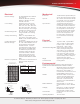
1 SERIES
C
2 ACTUATOR
1
A Handle, one per pole
B Handle, one per multipole unit
S Mid-Trip Handle, one per pole
T Mid-Trip, one per pole & Alarm Switch
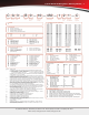
8 TERMINAL
15
1
10
Stud 10-32, threaded
2
11
Screw 10-32
3
12
Stud 1/4-20, threaded
4
11
Stud M5 x 0.8, threaded
5
11
Screw M5 x 0.8
6
12
Stud M6, threaded
7
13,15
0.250 Double Click Connect
8
15
1/4” Clip Terminal
9
12,15
7/16” Clip Terminal
A
14
Plug-In Stud
C
11,15
5/16” Clip Terminal
3 POLES
2
1 One
2 Two
3 Three
4 Four
5 Five
6 Six
4 CIRCUIT
3
A
3
Switch Only (no coil)
B Series Trip (current)
C Series Trip (voltage)
D
4
Shunt Trip (current)
E
4
Shunt Trip (voltage)
F
4
Relay Trip (current)
G
4
Relay Trip (voltage)
H
4,5
Dual Coil with Shunt Trip
Voltage Coil
K
4,5
Dual Coil with Relay Trip
Voltage Coil
5 AUXILIARY/ALARM SWITCH
0 without Aux Switch
2
S.P.D.T., 0.110 Q.C. Terminal
3 S.P.D.T., 0.139 Solder Lug
4 S.P.D.T., 0.110 Q.C. Terminal
(Gold Contacts)
6
S.P.S.T., 0.139 Solder Lug
8 S.P.S.T., 0.187 Q.C. Terminal
9 S.P.D.T., 0.187 Q.C. Terminal
6 FREQUENCY & DELAY
03
3
DC 50/60Hz, Switch Only
10
7
DC Instantaneous
11 DC Ultra Short
12 DC Short
14 DC Medium
16 DC Long
20
7
50/60Hz Instantaneous
21 50/60Hz Ultra Short
22 50/60Hz Short
24 50/60Hz Medium
26 50/60Hz Long
30
DC 50/60Hz Instantaneous
31 DC 50/60Hz Ultra Short
32 DC 50/60Hz Short
34 DC 50/60Hz Medium
36 DC 50/60Hz Long
42
8
50/60Hz Short, Hi-Inrush
44
8
50/60Hz Medium, Hi-Inrush
46
8
50/60Hz Long, Hi-Inrush
52
8
DC Short, Hi-Inrush
54
8
DC Medium, Hi-Inrush
56
DC Long, Hi-Inrush
7 CURRENT RATING (AMPERES)
020 0.020
025 0.025
030 0.030
035 0.035
040 0.040
045 0.045
050 0.050
055 0.055
060 0.060
065 0.065
070 0.070
075 0.075
080 0.080
085 0.085
090 0.090
095 0.095
210 0.100
215 0.150
220 0.200
225 0.250
230 0.300
235 0.350
240 0.400
245 0.450
250 0.500
255 0.550
260 0.600
265 0.650
270 0.700
275 0.750
280 0.800
285 0.850
290 0.900
295 0.950
410 1.000
512 1.250
415 1.500
517 1.750
420 2.000
522 2.250
425 2.500
527 2.750
430 3.000
435 3.500
440 4.000
445 4.500
450 5.000
455 5.500
460 6.000
465 6.500
470 7.000
475 7.500
480 8.000
485 8.500
490 9.000
495 9.500
610 10.000
710 10.500
611 11.000
711 11.500
612 12.000
712 12.500
613 13.000
614 14.000
615 15.000
616 16.000
617 17.000
618 18.000
620 20.000
622 22.000
624 24.000
625 25.000
630 30.000
635 35.000
640 40.000
650 50.000
660
9
60.000
670
9
70.000
680
9
80.000
685
9
85.000
690
9
90.000
695
9
95.000
810
9
100.000
CODE AMPERES
A06 6DC
A12 12DC
A18 18DC
A24 24DC
A32 32DC
A48 48DC
A65 65DC
J06 6AC
J12 12AC
J18 18AC
J24 24AC
J48 48AC
J65 65AC
K20 120AC
L40 240AC
CODE RATING
VOLTAGE COIL (NORMINAL RATED VOLTAGE)
7
9 ACTUATOR COLOR & LEGEND
16
Actuator Color
White
Black
Red
Green
Blue
Yellow
Gray
Orange
Black (short handle)
17
I-O
A
C
F
H
K
M
P
R
T
ON-OFF
B
D
G
J
L
N
Q
S
U
Dual
1
2
3
4
5
6
7
8
9
Legend Color
Black
White
White
White
White
Black
Black
Black
White
10 MOUNTING/ BARRIERS
MOUNTING STYLE
Threaded Insert
6-32 x 0.195 inches
6-32 x 0.195 inches
6-32 x 0.195 inches
ISO M3 x 5mm
ISO M3 x 5mm
ISO M3 x 5mm
with Handleguard
BARRIERS
no
yes
yes
no
yes
yes
no
1
A
C
18
2
B
D
18
E
17
VOLTAGE
300
300
300
300
300
300
300
Front Panel Snap-In, 1.00” [25.4mm] wide bezel
<
<
<
11 AGENCY APPROVAL
C UL Recognized, CSA Accepted
D VDE Certied, UL Recognized, CSA Accepted
E TUV Certied, UL Recognized, CSA Accepted
H UL489 Construction: VDE Certied, UL Recognized, CSA Accepted
I UL Rec. STD 1077, UL Rec. 1500 (ignition protected), CSA Accepted
L UL489 Construction: UL Recognized, CSA Accepted
R UL489 Construction: TUV Certied, UL Recognized, CSA Accepted
<
<
>
–
>
–