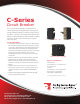
C-Series Circuit Breaker The C-Series hydraulic/magnetic circuit breakers are ideal for applications that require higher amperage and voltage handling capability in a smaller package. They are available in 1-6 poles, 0.02-100amps, UL Recognized up to 480VAC or 150VDC, UL489 Listed up to 240VAC or 125VDC, with choice of time delays, terminal options, actuator styles and colors.
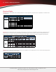
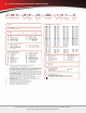
| C-Series – General Specifications Electrical Tables Table A: Lists UL Recognized & CSA Accepted configurations and performance capabilities as a Component Supplementary Protector 150 80-100 TC1, OLO, U3 150 101-175 TC, OLO, U3 Agency Code L Agency Code L Parallel Pole Notes for Table A: 1 Requires branch circuit backup with a UL LISTED Type K5 or RK5 fuse rated 15A minimum and no more than 4 times full load amps not to exceed 125A for 50 Amp or less rating and not to exceed 175 for 51 through 1
C-Series – General Specifications | 3 Electrical Tables Table B: Lists UL Recognized and CSA Accepted configurations and performance capabilities as a Manual Motor Controller. RELAY Notes for Table B: 1 UL recognized and CSA Accepted at 480V refers to 3 & 4 pole versions used in a 3Ø, wye connected circuit or 2-pole version connected with 2 poles breaking. 1Ø and backed up with series fusing as stated above in note 1.
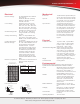
| C-Series – General Specifications Electrical Tables Table D: Lists UL Listed (489), CSA Certified (C22.2 No. 5.1-M) configuration and performance capabilities as a Molded Case Circuit Breaker. C SERIES TABLE D : UL489 LISTED BRANCH CIRCUIT BREAKERS CIRCUIT CONFIGURATION SERIES DUAL COIL INTERRUPTING CAPACITY (AMPS) WITHOUT FULL LOAD BACKUP FUSE AMPS CURRENT RATING VOLTAGE MAX. RATING FREQUENCY PHASE 80 DC --- 0.10 - 100 CONSTRUCTION NOTES 50,000 1 Limited to 2 Poles Max from 71 - 100 Amps.
C-Series – General Specifications | 5 Electrical Mechanical Maximum Voltage AC, 480 WYE/277 VAC, 50/60 Hz (see Table A.) UL489: AC,240 VAC. (Table D), 50/60 Hz, 125 VDC, UL 1077, 150 VDC, 277 VAC Standard current coils: 0.100, 0.250, 0.500, 0.750, 1.00, 2.50, 5.00, 7.50, 10.0, 15.0, 25.0, 30.0, 35.0, 40.0, 50.0, 60.0, 70.0, 80.0, 90.0 and 100 amps. Other ratings available, see Ordering Scheme. DC - 6V, 12V; AC - 120V; other ratings available, see Ordering Scheme. SPDT; 10.1 amps-250VAC, DC Aux.
| C-Series - Agency Certifications Agency Certifications: UL Recognized UL Standard 1077 Component Recognition Program as Protectors, Supplementary (Guide CCN/QVNU2, File E75596) UL Standard 508 Motor Controllers, Manual (Guide CCN/NLRV2, File E135367) UL Standard 1500 Protectors, Supplementary for Marine Electrical & Fuel Systems (Guide PEQZ2, File E75596) Ignition Protection UL Listed UL Standard 489 Circuit Breakers, Molded Case, (Guide DIVQ, File E129899) UL St
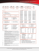
C-Series Handle UL Recognized – Ordering Scheme | 7 C A 3 — B 0 — 10 — 450 — 1 2 1 — C 1 Series 2 Actuator 4 Circuit 3 Poles 5 Aux/Alarm Switch 6 Frequency & Delay 2 ACTUATOR1 Handle, one per pole Handle, one per multipole unit Mid-Trip Handle, one per pole Mid-Trip, one per pole & Alarm Switch 3 POLES2 1 2 3 4 One Two 4 CIRCUIT3 A3 B C D4 E4 Switch Only (no coil) Series Trip (current) Series Trip (voltage) Shunt Trip (current) Shunt Trip (voltage) 5 AUXILIARY/ALARM SWITCH 0 2 3 4 without
| C-Series Handle Parallel Pole UL489A Listed – Ordering Scheme C A 2 — P 0 — D4 — 820 — 3 2 1 — M T 1 Series 2 Actuator 4 Circuit 3 Poles 5 Aux/Alarm Switch 6 Frequency & Delay 3 6 A 2 ACTUATOR1 Handle, one per pole Mid-Trip Handle, one per pole Mid-Trip, one per pole & Alarm Switch 3 POLES3 2 3 Two Three Series Trip (parallel pole) 5 AUXILIARY/ALARM SWITCH 0 2 3 4 without Aux Switch S.P.D.T., 0.110 Q.C. Terminal S.P.D.T., 0.139 Solder Lug S.P.D.T., 0.110 Q.C.
C-Series Handle UL489 Listed – Ordering Scheme | 9 C A 3 — B 0 — 14 — 450 — 1 2 1 — K G 1 Series 2 Actuator 4 Circuit 3 Poles 5 Aux/Alarm Switch 6 Frequency & Delay A B S T CODE 1 Handle, one per pole Handle, one per multipole unit Mid-Trip Handle, one per pole Mid-Trip, one per pole & Alarm Switch 3 POLES2 1 2 One 3 Two Three 4 CIRCUIT B Series Trip (current) 5 AUXILIARY/ALARM SWITCH3 0 2 3 4 without Aux Switch S.P.D.T., 0.110 Q.C. Terminal S.P.D.T., 0.139 Solder Lug S.P.D.T., 0.
| C-Series Sealed Toggle UL Recognized – Ordering Scheme C M 3 — B 0 — 10 — 450 — 1 0 1 — C 1 Series 2 Actuator 4 Circuit 3 Poles 5 Aux/Alarm Switch 6 Frequency & Delay M 1 Sealed Toggle, one per pole 3 POLES 1 2 One 4 CIRCUIT A2 B C D3 E3 Switch Only (no coil) Series Trip (current) Series Trip (voltage) Shunt Trip (current) Shunt Trip (voltage) 5 AUXILIARY/ALARM SWITCH 0 2 3 4 without Aux Switch S.P.D.T., 0.110 Q.C. Terminal S.P.D.T., 0.139 Solder Lug S.P.D.T., 0.110 Q.C.
C-Series Rocker UL Recognized – Ordering Scheme | 11 C C 3 — B 0 — 14 — 450 — 1 2 1 — D 1 Series 2 Actuator 4 Circuit 3 Poles 5 Aux/Alarm Switch 6 Frequency & Delay 1 SERIES C Single color J Vertical legend K Horizontal legend L No legend Push-To-Reset, Single color R Vertical legend U Horizontal legend V No legend Two Color Visi-Rocker C Indicate ON, vertical legend D Indicate ON, horizontal legend E Indicate ON, no legend F Indicate OFF, vertical legend G Indicate OFF, horizontal legend H Indi
| C-Series Rocker UL Listed – Ordering Scheme C C 3 — B 0 — 14 — 450 — 1 2 A — K G 1 Series 2 Actuator 4 Circuit 3 Poles 5 Aux/Alarm Switch 6 Frequency & Delay CODE 2 ACTUATOR1 Two Color Visi-Rocker C Indicate ON, vertical legend D Indicate ON, horizontal legend F Indicate OFF, vertical legend G Indicate OFF, horizontal legend Single color J Vertical legend K Horizontal legend ROCKER STYLE DESCRIPTIONS INDICATE "ON" INDICATE "OFF" SINGLE COLOR CODE "F" CODE "J" CODE "C" INDICATE COLOR L
C-Series Flat Rocker UL Recognized – Ordering Scheme | 13 C 1 2 — B 0 — 10 — 450 — 1 2 1 — E 1 Series 2 Actuator 4 Circuit 3 Poles 5 Aux/Alarm Switch 6 Frequency & Delay 1 SERIES C Two Color Visi-Rocker 1 Indicate OFF, vertical legend 2 Indicate OFF, horizontal legend Single color 3 Vertical legend 4 Horizontal legend Push-To-Reset, Visi-Rocker 5 Indicate OFF, vertical legend 6 Indicate OFF, horizontal legend Push-To-Reset , Single color 7 Vertical legend 8 Horizontal legend 3 POLES2 2 One 4
| C-Series Flat Rocker UL Listed – Ordering Scheme C 1 2 — B 0 — 14 — 450 — 1 2 A — K G 1 Series 2 Actuator 4 Circuit 3 Poles 5 Aux/Alarm Switch 6 Frequency & Delay CODE 210 215 220 225 230 235 240 245 250 255 260 265 270 275 280 285 290 2 ACTUATOR1 Two Color Visi-Rocker 1 Indicate OFF, vertical legend 2 Indicate OFF, horizontal legend Single color 3 Vertical legend 4 Horizontal legend Push-To-Reset, Visi-Rocker 5 Indicate OFF, vertical legend 6 Indicate OFF, horizontal legend Push-To-Reset ,
C-Series Handle – Circuit & Terminal Diagrams | 15 .960 [24.38] .311 DIA [Ø7.90] .558 [14.17] Notes: 1 2 3 All dimensions are in inches [millimeters]. Tolerance ±.020 [.51] unless otherwise specified. Available on Series Trip and Switch Only Circuits when called for on multi-pole units. Only one aux. switch is normally supplied, as viewed in mulit-pole identification scheme. 60 Johnson Avenue • Plainville, CT 06062–1177 • Phone: (860) 793–9281 • Fax: (860) 793–9231 Email: sales@carlingtech.
| C-Series Handle – Circuit & Terminal Diagrams LINE LOAD Notes: 1 2 3 4 All dimensions are in inches [millimeters]. Tolerance ±.020 [.51] unless otherwise specified. Schematic shown represents current trip circuits. Available only as special catalog number. 60 Johnson Avenue • Plainville, CT 06062–1177 • Phone: (860) 793–9281 • Fax: (860) 793–9231 Email: sales@carlingtech.com • www.carlingtech.
C-Series Handle – Form & Fit Drawings | 17 LINE LOAD Notes: 1 2 All dimensions are in inches [millimeters]. Tolerance ±.020 [.51] unless otherwise specified. 60 Johnson Avenue • Plainville, CT 06062–1177 • Phone: (860) 793–9281 • Fax: (860) 793–9231 Email: sales@carlingtech.com • www.carlingtech.
| C-Series Handleguard – Form & Fit Drawings LINE LOAD Notes: 1 2 All dimensions are in inches [millimeters]. Tolerance ±.020 [.51] unless otherwise specified. 60 Johnson Avenue • Plainville, CT 06062–1177 • Phone: (860) 793–9281 • Fax: (860) 793–9231 Email: sales@carlingtech.com • www.carlingtech.
C-Series Parellel Pole – Form & Fit Drawings | 19 LINE LOAD Notes: 1 2 All dimensions are in inches [millimeters]. Tolerance ±.020 [.51] unless otherwise specified. 60 Johnson Avenue • Plainville, CT 06062–1177 • Phone: (860) 793–9281 • Fax: (860) 793–9231 Email: sales@carlingtech.com • www.carlingtech.
| C-Series Sealed Toggle – Form & Fit Drawings LINE LOAD Notes: 1 2 All dimensions are in inches [millimeters]. Tolerance ±.020 [.51] unless otherwise specified. 60 Johnson Avenue • Plainville, CT 06062–1177 • Phone: (860) 793–9281 • Fax: (860) 793–9231 Email: sales@carlingtech.com • www.carlingtech.
C-Series Rocker – Circuit & Terminal Diagrams | 21 LINE LOAD Notes: 1 2 3 All dimensions are in inches [millimeters]. Tolerance ±.020 [.51] unless otherwise specified. Schematic shown represents current trip circuit. 60 Johnson Avenue • Plainville, CT 06062–1177 • Phone: (860) 793–9281 • Fax: (860) 793–9231 Email: sales@carlingtech.com • www.carlingtech.
| C-Series Rocker – Form & Fit Drawings LINE LOAD Notes: 1 2 3 4 Dimensions apply to all variations shown. Notice that circuit breaker line and load terminal orientation on indicate OFF is opposite of indicate ON. For pole orientation with horizontal legend, rotate front view clockwise 90°. All dimensions are in inches [millimeters]. Tolerance ±.020 [.51] unless otherwise specified. 60 Johnson Avenue • Plainville, CT 06062–1177 • Phone: (860) 793–9281 • Fax: (860) 793–9231 Email: sales@carlingtech.
C-Series Flat Rocker – Form & Fit Drawings | 23 LINE LOAD Notes: 1 2 3 For pole orientation with horizontal legend, rotate front view clockwise 90°. All dimensions are in inches [millimeters]. Tolerance ±.020 [.51] unless otherwise specified. 60 Johnson Avenue • Plainville, CT 06062–1177 • Phone: (860) 793–9281 • Fax: (860) 793–9231 Email: sales@carlingtech.com • www.carlingtech.
Worldwide Headquarters Carling Technologies, Inc. 60 Johnson Avenue • Plainville, CT 06062 Phone: (860) 793-9281 • Fax: (860) 793-9231 Email: sales@carlingtech.com • www.carlingtech.com East Region Sales Office, CT • ersm@carlingtech.com Midwest Region Sales Office, IL • mrsm@carlingtech.com West Region Sales Office, CA • wrsm@carlingtech.com Asia-Pacific Headquarters Carling Technologies, Asia-Pacific Ltd., Kowloon, Hong Kong Int + 852-2737-2277 • Fax: Int + 852-2736-9332 Email: sales@carlingtech.com.