
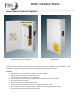
MNDC Instruction Manual


MNDC Instructions (continued)
6 | P a g e 1 0 - 0 06- 1 R E V : C
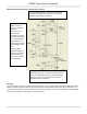
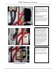
Battery Positive connections and shunt wiring
Wire exit to inverter
Din Rail mounted breakers
There are three 2” conduit
knock outs for inverter wire
exit. Carefully analyze the
possible wire exit paths to the
inverter. Six different shunt
placement options have been
provided in order to better
accommodate a wide range of
inverter options. Cables may
also exit the bottom in order
to reach an inverter not
mounted to the left of the
MNDC enclosure.
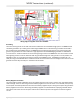
Note the 6AWG wire
connected to the lower
section of the inverter battery
breaker. This comes from the
output breaker from a charge
controller.
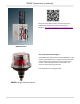
The inverter negative shunt
connection has the
corresponding negative circuit
from the charge controller and
negative from the DC-GFP.
Din Rail mount breakers
shown are for a solar charge
controller and a DC-GFP.
PV in is entering the MNDC
from the bottom in this photo.