
MNDC Instruction Manual


MNDC Instructions (continued)
4 | P a g e 1 0 - 0 06- 1 R E V : C
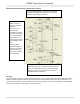
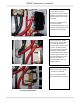
Wiring diagram supplied on the door of MNDC
Grounding
There are various ground circuits that need to be considered in the renewable energy system. The MNDC chassis
should be grounded to your earth ground rod through a 6AWG wire connected to the ground bus bar located in
the top left section of the MNDC chassis. The MNDC ground bus bar will then become your primary system DC
ground. The ground bus bar is also where DC surge suppressors like the MNSPD get grounded. It is advisable to
use one of the ½” conduit knockouts to mount a DC lightning arrestor to the MNDC box. It is also common to have
a DC lightning arrestor out at the PV Panels that are grounded through their own ground rod. In dry climates it is
advisable to also run a ground wire from the PV panels to the MNDC ground. The MNDC ground bus bar is an
ideal place to ground a DC-GFP when installed as well as the inverter chassis and the charge control chassis. Do the
grounds first since they normally lie in the bottom of the chassis.
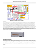
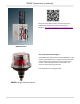
Ground Bus Bar
Battery Negative connection
The wiring diagram shows a 500 amp shunt. The voltage drop across the shunt is used to aid in calculating battery
state of charge. The shunt does not ground the battery negative circuit. If this shunt is not installed, then you may
use the 5/16” stud directly above the shunt area as a battery negative tie point. Using this tie point will ground the
battery negative to the chassis. Grounding the battery negative is not allowed when employing a DC-GFP device.
The inverter side of the shunt or the 5/16” stud are also an ideal tie point for PV negative or other DC negative
circuits.