
Specifications


-
46
-
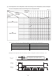
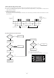
◆ Inspection of resistance value of sensor
Remove the connector and check the resistance value.
See the section of sensor characteristics on page 41.
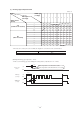
◆ Inspection power transistor
Remove the fasten terminal and test output voltage
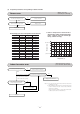
◆ Inspection of electronic expansion valve
To test if there is voltage.
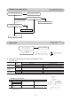
◆ Check point of outdoor unit
If the expansion valve does not operate as shown above, it is defective.
(Voltage is only applied to the electronic expansion valve when the valve opening
is being changed.)
Red to White
Red to Orange
Brown to Yellow
Brown to Blue
Normal if there is approximately DC 5 V 10 seconds
after the power asupply is turned on.
◆ Power source and serial signal inspection
to : AC 220/230/240V
1 to 2: AC 220/230/240V
2 to 3: Normal if the voltage oscillates between DC 0 and approx. 20V
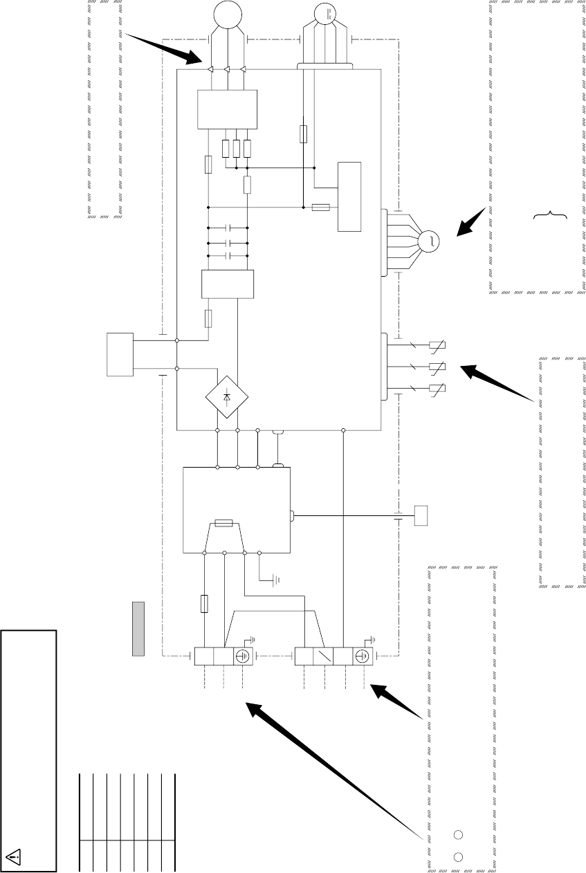
CAUTION
-
HIGH VOLTAGE
High voltage is produced in the control box. Don’t touch
electrical parts in the control box for 5 minutes after the
unit is stopped.
BK
BR
YE
WH
OR
YG
RD
Color symbol
Black
Brown
Yellow
White
Orange
Yellow/Green
Red
L
N
N
L
YG
T
1 Phase
220-240V 50Hz
Powewr Source
Indoor
unit
S-1
CNMAIN
250V
10A
F
S
IN
R
IN
R
OUT
BK
WH
G1
YG
BR
S
O
R
O
250V 20A
F
YG
CN20S
RD
WH
PWB ASSY (SUB)
20S
2
1
N
3
T
Outdoor unit
BK
WH
DS
WH
BK
RD
S
R
S-2
CNSUB
C-2
M
CNTH
CNEEV
t˚ t˚ t˚
222
Th
4
Th
5
Th
6
EEV
T2T1
250V 2A
F
F 250V 1A
250V 20A
F
R
OR
YE
CNFAN
PWBASSY (MAIN)
CIRCUIT
SWITCHING POWER
ACTIVE
FILTER
UNIT
++ +
BK
WH
RD
V
W
U
TRANSIS TOR
POWER
250V 20A
F
W
V
U
P
NU
NV
NW
M
M
3~
FMo
CM
(10) Outdoor unit inspection points