
Operating instructions


5
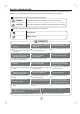
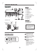
Parts names
Outdoor unit
OPERATING INSTRUCTIONS
Indoor unit
Signal receptor
(C
)
TEMP
A
U
T
O
C
O
O
L
D
R
Y
H
E
A
T
FA
N
H
I
G
H
M
E
D
L
O
W
M
ODE
FANSPE
ED
TIME
RON
SLEEP
ON/OFF
TIM
EROFF
A
IR
D
I
R
E
C
T
I
O
N
R
E
S
E
T
L
O
C
K
S
E
T
T
E
M
P
E
R
A
T
U
R
E
S
W
IN
G
L
E
D
D
I
S
P
L
A
Y
T
U
R
B
O
NOTE:
All the pictures in this manual
are for explanation purpose
only. Your air conditioner may
be slightly different.
The actual shape shall prevail.
1. Signal receptor
2. LCD Display panel
3. Panel frame
4. Chassis
5. Front panel
6. Horizontal louver
7. Vertical louver
8. Air filter
9. Manual control button
10.
11. Remote controller
12. Connecting pipe
13. Drain hose
14. Power cord
Remote controller holder
15.
16.
17. Stop valve
Connecting cable
Connective pipe
Indoor unit
Outdoor unit
6
5 7 8
9
1
2
3
4
14
13
12
11
Air outlet
Air inlet
Air inlet(rear)
Air inlet(side)
Air outlet
16
17
15
10
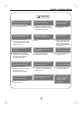
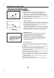
LCD display window
AUTO operation display
Displayed during Auto
operation.
OPERATION display
Displayed when the air
conditioner is in operation.
DEFROST operation
display
(For Heating & Cooling
model only):
Displayed when the air
conditioner starts defrosting
automatically or when the
warm air control feature is
activated in heating
operation.