
Operating instructions

5
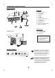
Parts names
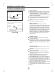
Outdoor unit
OPERATING INSTRUCTIONS
Indoor unit
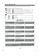
NOTE:
All the pictures in this manual
are for explanation purpose
only. Your air conditioner may
be slightly different.
The actual shape shall prevail.
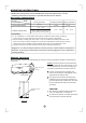
1. Display window
2. Front panel
3. Panel frame
4. Chassis
5. Air filter
6. Panel brace
7. Manual control button
8. Power cord
9. Connecting pipe
10. Drain hose
11. Remote controller holder
12. Remote controller
13.
14.
15. Stop valve
Connecting cable
Connective pipe
Indoor unit
Outdoor unit
6
5
7
1
2
3
4
8
10
9
12
Air outlet
Air inlet
Air inlet(rear)
Air inlet(side)
Air outlet
14
15
13
11
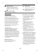
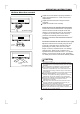
Display window
Signal receptor
DEFROST operation display
Displayed when the air conditioner
starts defrosting automatically or
when the warm air control feature is
activated in heating operation.
A
D
J
U
S
T
A
U
T
O
C
O
O
L
D
R
Y
H
E
A
T
FA
N
H
I
G
H
M
E
D
L
O
W
M
O
D
E
FA
N
S
P
E
E
D
D
I
R
E
C
T
I
O
N
/
S
W
I
N
G
T
I
M
E
R
O
N
S
L
E
E
P
O
N
/
O
F
F
T
I
M
E
R
O
F
F
S
E
L
F
C
L
E
A
N
R
E
S
E
T
L
O
C
K
S
ET
TE
MP
E
RA
T
URE
(
C
)
F
O
L
L
O
W
M
E
L
E
D
D
I
S
P
L
A
Y
C
L
E
A
N
A
I
R
T
U
R
B
O
This display is separated into five
zones. The zones illuminate based
on the compressor current frequency.
For example, higher frequency
will illuminate more zones.
Operation Frequency display