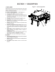
PS636 Series Gas Domestic & Std Export ENGLISH P/N 66639 December 2014 Rev. E PS636 Series Gas Ovens Model: • PS636G Gas Combinations: • • • Single Oven Double Oven (Two-Stack) Triple Oven (Three-Stack) OWNER'S OPERATING AND INSTALLATION MANUAL for domestic and standard export ovens ©2014 Middleby Marshall Inc. is a registered trademark of Middleby Marshall, Inc. All rights reserved.
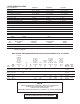
I. OVEN SPECIFICATIONS Single Oven 44″ (1118mm) 44-1/2″ (1130mm) 65-3/4″ (1670mm) 25-1/2″ (648mm) or 2 x 11” (279mm) Double Oven 62-3/8” (1635mm) 44-1/2” (1130mm) 65-3/4″ (1670mm) 25-1/2″ (648mm) or 2 x 11” (279mm) Triple Oven 69-3/4″ (1171mm) 44-1/2” (1130mm) 65-3/4″ (1670mm) 25-1/2″ (648mm) or 2 x 11” (279mm) Recommended Minimum Clearances Rear of Oven to Wall Control end of conveyor to Wall Non-control end of conveyor to Wall) Table 1-2: General Specifications PS636 GAS 0″ (0mm) 2″ (50.
SECTION 2 – INSTALLATION WARNING – After any conversions, readjustments, or service work on the oven: • Perform a gas leak test. • Test for proper combustion and gas supply. • Test for correct air supply, particularly to the • Check that the ventilation system is in operation. burner blower. WARNING - Keep the appliance area free and clear of combustibles. WARNING – The oven must be installed on an even (level) non-flammable flooring and any adjacent walls must be non-flammable.
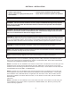
PS636 24” OVEN INSTALLATION REQUIRED KITS AND EQUIPMENT PS636 Gas Oven Installation Kit PS636 Single Oven Option Base w/ 15” Legs, Casters & Top Kit P/N 66129 PS636 Single Gas Oven 66331 1 PS636 Double Gas Oven 66332 PS636 Triple Gas Oven 66333 Type Of Installation PS636 Double Oven Option Base w/ 15” Legs, Casters & Top Kit P/N 66027 PS636 Triple Oven Option Base w/ 15” Legs, Casters & Top Kit P/N 6xxxx 1 1
III. VENTILATION SYSTEM B. NOTE THAT THE HOOD DIMENSIONS SHOWN IN FIGURE 2-5 ARE RECOMMENDATIONS ONLY. LOCAL, NATIONAL AND INTERNATIONAL CODES MUST BE FOLLOWED WHEN INSTALLING THE VENTILATION SYSTEM. ANY APPLICABLE CODES SUPERSEDE THE RECOMMENDATIONS SHOWN IN THIS MANUAL. IN AUSTRALIA COMPLIANCE TO REGULATIONS AS5601/AG601 IS MANDATORY. IMPORTANT Where national or local codes repression equipment or other supplementary equipment, DO NOT mount the equipment directly to the oven.
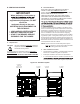
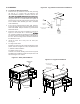
IV. ASSEMBLY Figure 2-6. Leg extension and casters installation A. Top Panel and Base Pad Assembly 1. Install the four leg extensions onto the base pad using the 3/8″-16 × 1″ screws, 3/8″ flat washers, and 3/8″ lockwashers supplied in the Base Pad Kit. See sion face OUTWARDS. One rear leg should be attached using three 3/8″-16 × 1″ screws and the 3/4″ eyebolt, as shown in Figure 2-6. This eyebolt acts as the anchor point for the restraint cable assembly (see Part C, Restraint Cable Installation). 2.
C. NOTE: DO NOT install top panel onto double or triple ovens until AFTER stacking the oven cavities. See Part B, Stacking. B. Restraint Cable Installation Because the oven is equipped with casters, a restraint cable assembly must be installed to limit the movement of the appliance without depending on the connector and the quick disconnect device or its associated piping. One end of the cable is anchored to the eyebolt on the rear surface of the oven’s base pad, while the other is anchored to the wall.
D. Conveyor Installation 1. 2. Figure 2-13. Conveyor placement Unfold the conveyor as shown in Figure 2-12. Then, begin to slide the conveyor into the end of the oven. The conveyor can only be installed from the end of the oven with the drive motor. Crumb tray support bracket Continue moving the conveyor into the oven until the frame protrudes equally from each end of the oven.
SECTION 4 - MAINTENANCE WARNING Before ANY cleaning or servicing of the oven, perform the following procedure: 1. 2. 3. Switch off the oven and allow it to cool. Do NOT service the oven while it is warm. Turn off the electric supply circuit breaker(s) and disconnect the electric supply to the oven. If it is necessary to move a gas oven for cleaning or servicing, disconnect the gas supply before moving the oven. When all cleaning and servicing is complete: 1.
21
Middleby-Marshall Model Number PS636G208-240 Volt 50/60Hz, 1 Phase SECTION 5 - WIRING DIAGRAM 23
NOTES 24
NOTES 25
WARNING Improper installation, adjustment, alteration, service or maintenance can cause property damage, injury or death. Read the installation, operating and maintenance instructions thoroughly before installing or servicing this equipment. NOTICE During the warranty period, ALL parts replacement and servicing should be performed by your Middleby Marshall Authorized Service Agent. Service that is performed by parties other than your Middleby Marshall Authorized Service Agent may void your warranty.