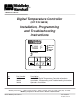
® A MIDDLEBY COMPANY Digital Temperature Controller (KIT P/N 36939) Installation, Programming and Troubleshooting Instructions 500 250 FF HEAT ON SET PT ACTUAL TEMP SP SP LOCK LOCK OVER TEMP Kit Contents Qty 1 1 1 Part Number 36056 36622 36940 Description On/Off-PID Digital Temperature Controller w/brackets Installation, Programming, and Troubleshooting Instructions Operators Instructions Middleby Marshall Inc.
INSTALLATION INSTRUCTIONS This manual provides instructions for conversion: from Analog Temperature Controller (A), PN 28071-0012 (without high-limit and cool down function)................................ to Analog Temperature Controller (A), PN 28071-0018 (with high-limit and cool down function)..................................... Digital Temperature Controller (B), PN 28071-0027 (with blue plastic face)................................................................
Unpacking The Digital Temperature Controller was checked before leaving the factory. Inspect the shipping container carefully for evidence of improper handling during shipment. In case of damage, make an immediate claim to the parts distributor from whom the unit was purchased. If the Digital Temperature Controller was shipped to you, notify the carrier without delay and file a claim.
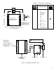
Installing the Digital Controller Step 1. Procedure Insert the Digital Temperature Controller into the same panel slot making sure the face of the controller is upright with the display on top and the push buttons on the bottom. 2.. Identify the two rectangular holes on top and bottom of the control case. Attach the two panel mounting brackets with the clips of the brackets and the heads of the screws pointing towards the rear of the new controller into these rectangular holes. See Figure 1. 3..
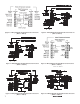
Table 1TABLE - Terminal Cross Reference 1 - TERMINAL CROSS REFERENCE TERMINAL ON NEW MODULE: TERMINAL ON OLD MODULE: FIGURE 2 - BACK SIDE OF TEMPERATURE CONTROLLER DESCRIPTION OF TERMINAL 500 Remove From Connect To Connect To 8 9 [13] [2] 7 10 [14] 6 NO NO CONNECT CONNECTION 11 [15] 12 [16] } [5] 5 [6] 4 [L2] L2 [L1] Standard On/Off output terminals for all models except 360EWB. 13 14 L1 15 [G] 16 } } } Not used on certain model gas and electric ovens.
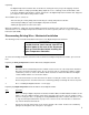
5. Check to be sure the oven’s thermocouple is the latest version flange mount style verses the obsolete version. See Figure 4 below. Flange Current Thermocouple cable PS360 (6.00”) PS200 (13.38”) Clip Obsolete Thermocouple Figure 4 - Current & Obsolete Thermocouple Comparison. The obsolete thermocouple is not compatible with the latest temperature controller, p/n 36056, and must be replaced with the latest thermocouple, kit p/n 33984 (300 Series ovens), and kit p/n 33985 (200 Series ovens).
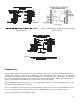
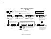
NOTE Be sure to replace any jumper wire specified in the wiring diagram. Table 2 - Wiring Configurations Oven Model Number Related Figure PS200 PS200 PS200 PS200 PS200 Gas Oven, 208-240V, 50/60Hz, 1 Ph, 3W...............................................................Figure 5 Gas Oven, 200V, 50/60Hz,1 Ph, 2W (Export Only)................................................Figure 5 Gas Oven, 208V, 50/60Hz,1 Ph, 2W (Export Only)................................................
F gure 5 W r ng D agram Show ng E ec r ca Connec ons Re er o Tab e 2 F gure 7 W r ng D agram Show ng E ec r ca Connec ons Re er o Tab e 2 F gure 6 W r ng D agram Show ng E ec r ca Connec ons Re er o Tab e 2 F gure 8 W r ng D agram Show ng E ec r ca Connec ons Re er o Tab e 2 ?@@@@@hW2@@@6X?g?@@@@@f?@@@@@@@@@@@@@@@6K ?O2@@@@6K?hf?O2@@@@6K?he?O2@@@@@6Kg?@@@@@h7@@@@@1?g?@@@@@f?@@@@@@@@@@@@@@@@@6X ?@@@@@@@@@@@@@@@@@@@g?O2@@@@@6K ?W2@@@@@@@@@6Xh?W2@@@@@@@@6K?g?W2@@@@@@@@@6Xf?@@@@@h@@@@@@@?g?@@@@@f?@@@@@@@@@@
Purp e Purp e Wh e F gure 11 W r ng D agram Show ng E ec r ca Connec ons Re er o Tab e 2 F gure 12 W r ng D agram Show ng E ec r ca Connec ons Re er o Tab e 2 O2@@@@@6K? ?O2@@@@@6K ?O2@@@@@6K ?O2@@@@@6K W2@@@@@@@@@6X? @@@@@? ?O2@@@6X ?W2@@@@@@@@@6X ?@@@@@ ?O2@@@@@@@@@6X ?W2@@@@@@@@@6Xh@@@@@@@@@@@@@@@@@@ O2@@@6K?he?O2@@@6KhfO2@@@6K? ?W&@@@@@@@@@@@)X @@@@@? ?W2@@@@@@)X? ?O2@@@@6K?heW2@@@@6Khe?O2@@@6K W&@@@@@@@@@@@)X? ?@@@@@ ?W2@@@@@@@@@@@@)X? W&@@@@@@@@@@@)X?g@@@@@@@@@@@@@@@@@@ W2@@@@@@@6X?g?W2@@@@@@@6XhW2
9 Digital Temperature Controller PN 36056 Service instructions Push the lock key and the service key together to reach SP LOK, then use the service key to step through the other functions listed below. Use the arrow keys to change the function settings. Factory settings are as shown below.
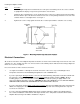
Digital Temperature Controller P/N 36056 Operators Instructions HEAT ON: Controller calling for heat when lit. High flame on. Once the oven reaches temperature the LED will cycle on and off. DISPLAY: Temperature displayed in degrees Fahrenheit or Celsius SP LOCK: N/A to operator OVER TEMP: Over Temperature condition when lit. On above 650ºF(343ºC) 250 250 FF HEAT ON SET PT ACTUAL TEMP SP LOCK LOCK OVER TEMP SET PT: Lit when controller is displaying set point temperature.
Diagnostic Error Messages The controller runs background tests during normal operation. If a problem with the background tests occurs, an error message is shown (flashing) in the Display. These are called Diagnostic Error Messages (Table 3). Table 3 - Diagnostic Error Messages Display rPLC Flashes on the display alternately with temperature indicating that the controller’s internal diagnostics test has failed.