
User Manual

22
22
44
44
11
11
33
33
MM
MM
OO
OO
TT
TT
OO
OO
RR
RR
RR
RR
EE
EE
LL
LL
AA
AA
YY
YY
MM
MM
OO
OO
TT
TT
OO
OO
RR
RR
WW
WW
II
II
TT
TT
HH
HH
II
II
NN
NN
TT
TT
EE
EE
RR
RR
NN
NN
AA
AA
LL
LL
II
II
NN
NN
TT
TT
EE
EE
RR
RR
LL
LL
OO
OO
CC
CC
KK
KK
SS
SS
WW
WW
II
II
TT
TT
CC
CC
HH
HH
TT
TT
TT
TT
11
11
22
22
GG
GG
NN
NN
DD
DD
CC
CC
OO
OO
MM
MM
BB
BB
II
II
NN
NN
AA
AA
TT
TT
II
II
OO
OO
NN
NN
VV
VV
AA
AA
LL
LL
VV
VV
EE
EE
YY
YY
YY
YY
BB
BB
KK
KK
BB
BB
KK
KK
BB
BB
KK
KK
BB
BB
LL
LL
((
((
YY
YY
))
))
RR
RR
((
((
YY
YY
))
))
RR
RR
((
((
YY
YY
))
))
WW
WW
((
((
BB
BB
KK
KK
))
))
MODEL E20B ECONOMITE
TT
TT
RR
RR
AA
AA
NN
NN
SS
SS
FF
FF
OO
OO
RR
RR
MM
MM
EE
EE
RR
RR
NN
NN
EE
EE
UU
UU
TT
TT
RR
RR
AA
AA
LL
LL
11
11
22
22
00
00
//
//
11
11
//
//
66
66
00
00
HH
HH
OO
OO
TT
TT
TT
TT
HH
HH
EE
EE
RR
RR
MM
MM
OO
OO
SS
SS
TT
TT
AA
AA
TT
TT
OO
OO
RR
RR
22
22
44
44
VV
VV
OO
OO
PP
PP
EE
EE
RR
RR
AA
AA
TT
TT
II
II
NN
NN
GG
GG
CC
CC
OO
OO
NN
NN
TT
TT
RR
RR
OO
OO
LL
LL
..
..
II
II
FF
FF
NN
NN
OO
OO
TT
TT
UU
UU
SS
SS
EE
EE
DD
DD
,,
,,
JJ
JJ
UU
UU
MM
MM
PP
PP
EE
EE
RR
RR
TT
TT
--
--
TT
TT
SS
SS
EE
EE
RR
RR
II
II
EE
EE
SS
SS
CC
CC
OO
OO
NN
NN
NN
NN
EE
EE
CC
CC
TT
TT
AA
AA
LL
LL
LL
LL
11
11
22
22
00
00
VV
VV
OO
OO
PP
PP
EE
EE
RR
RR
AA
AA
TT
TT
II
II
NN
NN
GG
GG
AA
AA
NN
NN
DD
DD
//
//
OO
OO
RR
RR
LL
LL
II
II
MM
MM
II
II
TT
TT
CC
CC
OO
OO
NN
NN
TT
TT
RR
RR
OO
OO
LL
LL
SS
SS
FF
FF
UU
UU
SS
SS
EE
EE
DD
DD
DD
DD
II
II
SS
SS
CC
CC
OO
OO
NN
NN
NN
NN
EE
EE
CC
CC
TT
TT
BB
BB
LL
LL
WW
WW
((
((
BB
BB
KK
KK
))
))
TT
TT
HH
HH
TT
TT
RR
RR
TT
TT
EE
EE
RR
RR
MM
MM
II
II
NN
NN
AA
AA
LL
LL
SS
SS
TT
TT
RR
RR
II
II
PP
PP
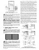
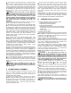
CONNECTION DIAGRAM
SS
SS
PP
PP
LL
LL
II
II
CC
CC
EE
EE
BB
BB
KK
KK
BB
BB
KK
KK
((
((
WW
WW
))
))
DD
DD
AA
AA
SS
SS
HH
HH
EE
EE
DD
DD
::
::
WW
WW
II
II
RR
RR
II
II
NN
NN
GG
GG
AA
AA
NN
NN
DD
DD
CC
CC
OO
OO
MM
MM
PP
PP
OO
OO
NN
NN
EE
EE
NN
NN
TT
TT
SS
SS
BB
BB
YY
YY
II
II
NN
NN
SS
SS
TT
TT
AA
AA
LL
LL
LL
LL
EE
EE
RR
RR
22
22
11
11
NN
NN
EE
EE
UU
UU
TT
TT
RR
RR
AA
AA
LL
LL
MM
MM
OO
OO
TT
TT
OO
OO
RR
RR
WW
WW
((
((
BB
BB
KK
KK
))
))
BB
BB
KK
KK
MM
MM
II
II
44
44
22
22
HH
HH
OO
OO
TT
TT
11
11
22
22
00
00
VV
VV
CC
CC
OO
OO
NN
NN
TT
TT
RR
RR
OO
OO
LL
LL
SS
SS
11
11
22
22
00
00
//
//
11
11
//
//
66
66
00
00
WW
WW
((
((
BB
BB
KK
KK
))
))
BB
BB
KK
KK
YY
YY
BB
BB
LL
LL
((
((
YY
YY
))
))
TT
TT
((
((
LL
LL
EE
EE
FF
FF
TT
TT
))
))
TT
TT
((
((
RR
RR
II
II
GG
GG
HH
HH
TT
TT
))
))
22
22
44
44
VV
VV
22
22
44
44
VV
VV
CC
CC
OO
OO
NN
NN
TT
TT
RR
RR
OO
OO
LL
LL
II
II
FF
FF
NN
NN
OO
OO
TT
TT
UU
UU
SS
SS
EE
EE
DD
DD
,,
,,
JJ
JJ
UU
UU
MM
MM
PP
PP
EE
EE
RR
RR
TT
TT
--
--
TT
TT
MM
MM
11
11
33
33
MM
MM
OO
OO
TT
TT
OO
OO
RR
RR
RR
RR
EE
EE
LL
LL
AA
AA
YY
YY
SS
SS
PP
PP
SS
SS
TT
TT
NN
NN
..
..
OO
OO
..
..
BB
BB
LL
LL
YY
YY
RR
RR
((
((
YY
YY
))
))
II
II
NN
NN
TT
TT
EE
EE
RR
RR
LL
LL
OO
OO
CC
CC
KK
KK
SS
SS
WW
WW
II
II
TT
TT
CC
CC
HH
HH
RR
RR
((
((
YY
YY
))
))
BB
BB
KK
KK
((
((
WW
WW
))
))
CC
CC
OO
OO
MM
MM
BB
BB
II
II
NN
NN
AA
AA
TT
TT
II
II
OO
OO
NN
NN
VV
VV
AA
AA
LL
LL
VV
VV
EE
EE
GG
GG
RR
RR
OO
OO
UU
UU
NN
NN
DD
DD
BB
BB
AA
AA
RR
RR
TT
TT
RR
RR
TT
TT
HH
HH
SCHEMATIC
SS
SS
OO
OO
LL
LL
II
II
DD
DD
RR
RR
OO
OO
UU
UU
NN
NN
DD
DD
::
::
BB
BB
UU
UU
RR
RR
NN
NN
EE
EE
RR
RR
SS
SS
TT
TT
RR
RR
II
II
PP
PP
OO
OO
PP
PP
EE
EE
NN
NN
RR
RR
OO
OO
UU
UU
NN
NN
DD
DD
::
::
CC
CC
OO
OO
MM
MM
PP
PP
OO
OO
NN
NN
EE
EE
NN
NN
TT
TT
5
LEGEND
5
OO
OO
PP
PP
TT
TT
II
II
OO
OO
NN
NN
AA
AA
LL
LL
RR
RR
EE
EE
DD
DD
UU
UU
NN
NN
DD
DD
AA
AA
NN
NN
TT
TT
VV
VV
AA
AA
LL
LL
VV
VV
EE
EE
BB
BB
KK
KK
SS
SS
PP
PP
LL
LL
II
II
CC
CC
EE
EE
BB
BB
KK
KK
SS
SS
OO
OO
LL
LL
II
II
DD
DD
::
::
WW
WW
II
II
RR
RR
II
II
NN
NN
GG
GG
AA
AA
NN
NN
DD
DD
CC
CC
OO
OO
MM
MM
PP
PP
OO
OO
NN
NN
EE
EE
NN
NN
TT
TT
SS
SS
BB
BB
YY
YY
MM
MM
II
II
DD
DD
CC
CC
OO
OO
CAUTION: Do not add any power consuming devices in the low voltage circuit as overloading of the transformer
can result. Do not use Motor Relay to operate any external devices as overloading of motor relay contacts can result.
NOTE: If any of the original wiring as supplied with the conversion burner must be replaced, it must be replaced with type TFF wire or
its equivalent.
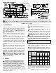
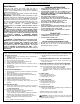
Capacities shown are for a total pressure drop of 0.3"
W.C. For a higher permissible pressure drops, consult
your fuel supplier. Source, Gas Engineering Handbook -
1974
TABLE 2 Supply Pipe Capacities in MBH
20
90
145
190
225
100
60
80
125
150
225
225
TYPE
OF GAS
NATURAL
PROPANE
NATURAL
PROPANE
NATURAL
PROPANE
NATURAL
PIPE
SIZE
1/2
3/4
1
11/4
APPROX. CAPACITY - MBH
LENGTH OF PIPE
10
130
200
225
40
60
100
130
205
225
60
50
80
105
165
195
-4-
FIGURE 5. Wiring Diagram
V ELECTRICAL
Installation wiring and grounding of the burner must
conform to local codes or, in their absence in the United
States to National Electric Code, ANSI/NFPA No. 70
latest edition; in Canada, to Canadian Electrical Code
Part 1, CSA Standard C22.1.
■ Use 14 gage copper wire, for line voltage wiring. Be
sure to hook up to a permanently live circuit. Provide a
fused on-off disconnect switch carrying a minimum 3
amp fuse.
■ The frame of the burner should be well grounded. A
terminal is provided on the terminal strip for positive
grounding where insulated pipe couplings are used or
where any doubt exists regarding grounding sufficiency.
■ Confirm that the polarity is correct -- hot wire to strip
terminal 1, neutral 2 and that the neutral line is not subject
to induced low voltage (check 2 to ground) from other
equipment .
■ Each installation must include suitable limit controls.
Existing oil burner combination limit and operating controls
containing cad cells.are NOT SUITABLE for gas burner
use.
■ Set the thermostat heat anticipator for total current draw
handled by the thermostat. The current draw of the
Economite 24V operating circuit is 0.3 amp on E20B
(NATURAL) and 0.7 amp on E20BP (PROPANE). Setting
may have to be increased on steam or gravity systems.
CAUTION: Label all wires prior to disconnection
when servicing controls. Wiring errors can cause
improper and dangerous operation. Verify proper
operation after servicing.
VI PIPING
CAUTION: The available gas pressure should be
within the limits shown in SPECIFICATIONS section.
If the supply pressure exceeds the 14.0" W.C.
maximum, a suitable intermediate main regulator rated
for main and pilot loads must be installed ahead of the
main manual shut-off valve shown in Figure 5.
■ The burner gas supply piping should branch off from the
main line as close to the gas meter as possible. Do not
connect to the bottom of a horizontal section. Use new
black pipe and malleable fittings free of cutting and
threading burrs or defects.
■ Provide a sediment trap, union and 1/8" pressure tap in
piping close to burner as shown in Figure 5.
■ Use pipe joint compound resistant to Liquid Petroleum
Gases.
■ Piping must also comply with local codes.
■ To obtain the maximum firing rate of 225 MBH, the
NATURAL and PROPANE gas supply piping must be sized
to provide a minimum of 5.0" W.C. pressure to the inlet of the
combination valve when the burner and all other gas
appliances are on.
CAUTION: Because it is difficult to accurately con-
trol pressure during supply pipe leak test, it is recom-
mend that the Combination Valve be disconnected. Ex-
posing the Combination Valve to pressures over 1/2
PSIG will damage the valve and void its warranty.
DANGER: Explosion hazard. Do not use oxygen for
pressure testing. An explosion could occur during initial
start-up.
■ If the burner piping must be rearranged because of space
limitations, be sure to carry out the general arrangement
shown in Figure 5. Install the combination valve in any
position except up-side down.
■ When the burner is installed in the vestibule of equipment,
it is recommended that the combination valve be left
adjacent to the Burner within the vestibule and the Main
Manual Shut-Off Valve be installed outside.