
Operator Manual

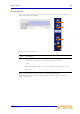
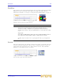
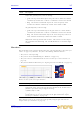
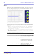
Table Of Contents
- F16, F16R, F24 and F32 Professional Audio Mixing Consoles
- Important safety instructions
- Other important information
- Contents
- Chapter 1: Introduction
- Chapter 2: Getting Started
- Chapter 3: Using The VeniceF With FireWire
- Chapter 4: Working With The Console
- Chapter 5: Mono Input Channel
- Chapter 6: Dual Stereo Input Channel
- Chapter 7: Output Section
- Appendix A: Functional Block Diagrams
- Appendix B: Technical Specification
- Appendix C: Application Notes
- Appendix D: Crib Sheets
- Appendix E: Best Grounding Practice
- Appendix F: Service Information
- FEDERAL COMMUNICATIONS COMMISSION COMPLIANCE INFORMATION

Rear panel 33
VeniceF
Operator Manual
Rear panel
The VeniceF channel inputs are located on the rear panel of the console and each
channel comprises the following.
Mono input channel connectors
The direct out and insert points operate at a nominal level of 0dBu.
Balanced XLR and Jack inputs are conventionally wired (see Table 1 “Connector
pinouts” on page 12).
Item Description
1 insert connector Insert point on a single 1/4” TRS Jack socket. This is
unbalanced and requires a conventionally-wired insert lead.
2 direct out connector Direct output on a single, balanced 1/4” TRS Jack
socket.
3 line in connector Line in on a single, balanced 1/4” TRS Jack socket.
4 mic connector Mic input on a single, balanced XLR female chassis
connector.
1
2
3
4