
Operator Manual
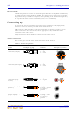
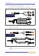
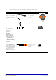

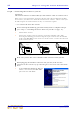
Table Of Contents
- F16, F16R, F24 and F32 Professional Audio Mixing Consoles
- Important safety instructions
- Other important information
- Contents
- Chapter 1: Introduction
- Chapter 2: Getting Started
- Chapter 3: Using The VeniceF With FireWire
- Chapter 4: Working With The Console
- Chapter 5: Mono Input Channel
- Chapter 6: Dual Stereo Input Channel
- Chapter 7: Output Section
- Appendix A: Functional Block Diagrams
- Appendix B: Technical Specification
- Appendix C: Application Notes
- Appendix D: Crib Sheets
- Appendix E: Best Grounding Practice
- Appendix F: Service Information
- FEDERAL COMMUNICATIONS COMMISSION COMPLIANCE INFORMATION

14 Chapter 2: Getting Started
VeniceF
Operator Manual
Other connections
The section gives details of the other VeniceF interconnections.
Description Example Pinouts Example of socket
4-pin, male XLR
chassis connector(s)
on the rear panel for
connecting 12V/5W
lamp(s)
1 = N/A
2 = N/A
3 = ground
4 = 12V
1-off socket in the
FireWire section of
the rear panel for
connecting a 6-pin,
FireWire 400
connector
Important:
If you have any
audio problems
these may be due
to ground loops
(see Appendix
E "Best Grounding
Practice" on
page 103).
N/A
Headphones socket in
the local monitor
section of the control
surface for connecting
a 1/4” TRS Jack plug.
There is also one
under the armrest on
the desktop versions.
1 (tip) = left
2 (ring) = right
3 (sleeve) =
ground
4
1
3
2
123