
Operator Manual


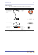


Table Of Contents
- Contents
- Overview
- Chapter 1: Introduction
- Chapter 2: PRO2 Live Audio System
- Chapter 3: About The PRO2 Control Centre
- Getting Started
- Basic Operation Of The PRO2
- Chapter 5: Before You Start
- Chapter 6: Working With The PRO2 Control Centre
- Chapter 7: Navigation
- Chapter 8: Patching
- Introduction
- Terms used in PRO2 patching
- About the Patching screen
- Patching tooltips
- About the patching procedure
- Configuring the devices
- Setting up the I/O rack device(s)
- How to patch
- Chapter 9: Basic Operation
- Setting a mic amplifier’s input gain
- Setting the high and low pass filters
- Input equalisation (E zone)
- Input dynamics processing (D zone)
- Output processing
- Using VCA/POPulation groups
- Setting up a mix
- Setting up the effects rack
- Simple routing to master stereo outputs
- Automation
- Configuring the inputs and outputs
- Using copy and paste
- User library (presets)
- Surround panning
- Area B operation
- Saving your show files to a USB memory stick
- External AES50 synchronisation
- Security (locking mode)
- Advanced Operation And Features
- Chapter 10: Stereo Linking
- Chapter 11: Panning
- Chapter 12: Soloing
- Chapter 13: Muting
- Chapter 14: Monitors And Communications
- Chapter 15: Graphic Equaliser (GEQ)
- Chapter 16: Internal Effects
- Chapter 17: Control Groups
- Chapter 18: Copy And Paste
- Chapter 19: Assignable Controls
- Chapter 20: Scenes And Shows (Automation)
- About automation
- Automation controls
- Automation screen
- Using the right-click menu
- Scenes
- Scene contents
- Point scenes
- Numbering and navigation
- Initial snapshot scene (scene 0)
- Date and time
- Scene cue list
- Editing scene properties
- Adding a new scene
- Copying and deleting scenes
- Changing the order of the scenes
- Overriding store scope
- Using patching in automation
- Using zoom
- Show files
- Rehearsals
- Safes
- Chapter 21: Scope (Automation)
- Chapter 22: Events (Automation)
- Chapter 23: Crossfades (Automation)
- Chapter 24: User Libraries (Presets)
- Chapter 25: File Management
- Chapter 26: Using Other Devices With The PRO2
- Chapter 27: Changing The Preferences
- Setting the meter preferences
- Configuring a virtual soundcheck
- Configuring playback
- Restoring the PRO2 defaults
- Checking the build information
- Using patching in automation
- Selecting the surround mode
- Setting the time and date
- Setting the user interface preferences
- Setting the navigation mode
- VCA unfolding
- Changing the default input/output names
- On-scene store
- Changing the signal processing preferences
- Adjusting PRO2 illumination
- Selecting the function of the foot switch(es)
- Selecting the fan speed
- Remote control server
- Configuring the channels, groups and internal units
- Chapter 28: Delay Compensation (Latency)
- Description
- Chapter 29: Panel Connections
- Chapter 30: Input Channels
- Chapter 31: Output Channels
- Chapter 32: GUI Menu
- Appendices
- Appendix A: Application Notes
- Appendix B: Functional Block Diagrams
- Appendix C: Technical Specification
- PRO2 general statistics
- PRO2 general specifications
- PRO2 audio performance specifications
- PRO2 system inputs and outputs
- DL251 I/O box - analogue inputs
- DL251 I/O box - analogue outputs
- DL251 I/O box - MIDI
- DL251 I/O box - digital system inputs and outputs
- PRO2 control surface - DSP/router system inputs and outputs
- PRO2 control surface - analogue audio system inputs
- PRO2 control surface - analogue audio system outputs
- PRO2 control surface - digital audio system inputs and outputs
- PRO2 control surface - control data system inputs and outputs
- PRO2 control centre - miscellaneous inputs and outputs
- Inputs and output characteristics
- Main processing functions
- Status functions
- Appendix D: Troubleshooting
- Appendix E: Updating The PRO2 Host Software
- Appendix F: Parameters Affected By Scope
- Appendix G: Parameters Affected By Automate Patching
- Appendix H: Parameters Protected By Safes
- Appendix I: Parameters Affected By Copy And Paste
- Appendix J: Parameters Affected By Stereo Linking
- Appendix K: Parameters Copied Through Scenes
- Appendix L: Service Information
- Glossary
- Other important information
- 1 Register online. Please register your new Midas equipment right after you purchase it by visiting www.midasconsoles.com. Registering your purchase using our simple online form helps us to process your repair claims more quickly and efficiently. Als...
- 2 Malfunction. Should your MUSIC Group Authorized Reseller not be located in your vicinity, you may contact the MUSIC Group Authorized Fulfiller for your country at www.midasconsoles.com. If your country is not listed please contact the “United Kin...
- 3 Power Connections. Before plugging the unit into a power socket, please make sure you are using the correct mains voltage for your particular model. Faulty fuses must be replaced with fuses of the same type and rating without exception.
- FEDERAL COMMUNICATIONS COMMISSION COMPLIANCE INFORMATION

Making up a rack 27
PRO2 Live Audio System
Owner’s Manual
Special accessories
To comply with part 15 of the FCC Rules, any special accessories (that is, items that
cannot be readily obtained from multiple retail outlets) supplied with this equipment
must be used with this equipment; do not use any alternatives as they may not fulfil
the RF requirement.
Making up a rack
If you are making up a rack, there are careful considerations to be addressed
beforehand, which are outlined in this section.
Outboard equipment racks
To ensure the correct installation and function of the outboard equipment, such as the
DL251 Audio System I/O and DN9696 recorder, racks must meet the following general
requirements.
• Shock mounting (for non-installation environments): The racks must provide
adequate shock protection of the units they house by incorporating appropriately-
designed shock protection methods, for example, a foam-suspended rack or a frame
suspended on anti-vibration mounts etc.
• Ventilation: Midas rack units have been designed such that their internal ventilation
airflow is drawn in through the front of the unit and expelled though the rear. To
facilitate this, rack design must ensure that cool air can flow freely through the rack
in the same direction, that is, in through the front of the rack and out through the
rear. Situations where the air flows in a circular direction around and through a unit
must be prevented. Midas recommends that racks with fully opening front and rear
doors are used.
Note: Never combine units in the same rack that have been designed for a
ventilation air flow direction other than that for the PRO2 units. To avoid this, we
recommend that any non-PRO2 units are housed separately.
• Rack mount supports: Always secure the rear of the units to the rack via their rear
rack mount support brackets. These brackets are fitted to every PRO2 unit and are
recommended for use in touring applications. The rack mount support fixing hole
centres are at a depth of approximately 395 mm from the front panel (this
dimension may differ slightly on the DN9696).
• Handles on rack case: You must ensure that there are sufficient external handles
fitted to the rack casing to enable the rack to be manoeuvred easily and safely, and
by the amount of personnel suitable for the task. Also, these handles must be fit for
purpose.
• Clearance at rear of units: To ensure an adequate clearance at the rear of the
units, we recommend that the rack depth, that is, the distance from the front rack
strip to the rear of the rack, is a minimum of 700 mm.
• Securing the cables: We recommend that the cables at the rear of the units be
tidied using lacing bars and cable ties. This should provide optimum access to the
rear of the units for connecting other cables, switching the units on/off, etc., and
give maximum visibility of the units’ LEDs for determining communication status,
link status, condition of audio etc.