
Operator Manual
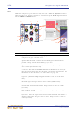

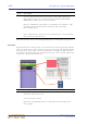

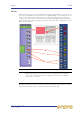

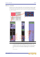
Table Of Contents
- Contents
- Overview
- Chapter 1: Introduction
- Chapter 2: PRO2 Live Audio System
- Chapter 3: About The PRO2 Control Centre
- Getting Started
- Basic Operation Of The PRO2
- Chapter 5: Before You Start
- Chapter 6: Working With The PRO2 Control Centre
- Chapter 7: Navigation
- Chapter 8: Patching
- Introduction
- Terms used in PRO2 patching
- About the Patching screen
- Patching tooltips
- About the patching procedure
- Configuring the devices
- Setting up the I/O rack device(s)
- How to patch
- Chapter 9: Basic Operation
- Setting a mic amplifier’s input gain
- Setting the high and low pass filters
- Input equalisation (E zone)
- Input dynamics processing (D zone)
- Output processing
- Using VCA/POPulation groups
- Setting up a mix
- Setting up the effects rack
- Simple routing to master stereo outputs
- Automation
- Configuring the inputs and outputs
- Using copy and paste
- User library (presets)
- Surround panning
- Area B operation
- Saving your show files to a USB memory stick
- External AES50 synchronisation
- Security (locking mode)
- Advanced Operation And Features
- Chapter 10: Stereo Linking
- Chapter 11: Panning
- Chapter 12: Soloing
- Chapter 13: Muting
- Chapter 14: Monitors And Communications
- Chapter 15: Graphic Equaliser (GEQ)
- Chapter 16: Internal Effects
- Chapter 17: Control Groups
- Chapter 18: Copy And Paste
- Chapter 19: Assignable Controls
- Chapter 20: Scenes And Shows (Automation)
- About automation
- Automation controls
- Automation screen
- Using the right-click menu
- Scenes
- Scene contents
- Point scenes
- Numbering and navigation
- Initial snapshot scene (scene 0)
- Date and time
- Scene cue list
- Editing scene properties
- Adding a new scene
- Copying and deleting scenes
- Changing the order of the scenes
- Overriding store scope
- Using patching in automation
- Using zoom
- Show files
- Rehearsals
- Safes
- Chapter 21: Scope (Automation)
- Chapter 22: Events (Automation)
- Chapter 23: Crossfades (Automation)
- Chapter 24: User Libraries (Presets)
- Chapter 25: File Management
- Chapter 26: Using Other Devices With The PRO2
- Chapter 27: Changing The Preferences
- Setting the meter preferences
- Configuring a virtual soundcheck
- Configuring playback
- Restoring the PRO2 defaults
- Checking the build information
- Using patching in automation
- Selecting the surround mode
- Setting the time and date
- Setting the user interface preferences
- Setting the navigation mode
- VCA unfolding
- Changing the default input/output names
- On-scene store
- Changing the signal processing preferences
- Adjusting PRO2 illumination
- Selecting the function of the foot switch(es)
- Selecting the fan speed
- Remote control server
- Configuring the channels, groups and internal units
- Chapter 28: Delay Compensation (Latency)
- Description
- Chapter 29: Panel Connections
- Chapter 30: Input Channels
- Chapter 31: Output Channels
- Chapter 32: GUI Menu
- Appendices
- Appendix A: Application Notes
- Appendix B: Functional Block Diagrams
- Appendix C: Technical Specification
- PRO2 general statistics
- PRO2 general specifications
- PRO2 audio performance specifications
- PRO2 system inputs and outputs
- DL251 I/O box - analogue inputs
- DL251 I/O box - analogue outputs
- DL251 I/O box - MIDI
- DL251 I/O box - digital system inputs and outputs
- PRO2 control surface - DSP/router system inputs and outputs
- PRO2 control surface - analogue audio system inputs
- PRO2 control surface - analogue audio system outputs
- PRO2 control surface - digital audio system inputs and outputs
- PRO2 control surface - control data system inputs and outputs
- PRO2 control centre - miscellaneous inputs and outputs
- Inputs and output characteristics
- Main processing functions
- Status functions
- Appendix D: Troubleshooting
- Appendix E: Updating The PRO2 Host Software
- Appendix F: Parameters Affected By Scope
- Appendix G: Parameters Affected By Automate Patching
- Appendix H: Parameters Protected By Safes
- Appendix I: Parameters Affected By Copy And Paste
- Appendix J: Parameters Affected By Stereo Linking
- Appendix K: Parameters Copied Through Scenes
- Appendix L: Service Information
- Glossary
- Other important information
- 1 Register online. Please register your new Midas equipment right after you purchase it by visiting www.midasconsoles.com. Registering your purchase using our simple online form helps us to process your repair claims more quickly and efficiently. Als...
- 2 Malfunction. Should your MUSIC Group Authorized Reseller not be located in your vicinity, you may contact the MUSIC Group Authorized Fulfiller for your country at www.midasconsoles.com. If your country is not listed please contact the “United Kin...
- 3 Power Connections. Before plugging the unit into a power socket, please make sure you are using the correct mains voltage for your particular model. Faulty fuses must be replaced with fuses of the same type and rating without exception.
- FEDERAL COMMUNICATIONS COMMISSION COMPLIANCE INFORMATION

258 Chapter 30: Input Channels
PRO2 Live Audio System
Owner’s Manual
In the GUI channel strip, the EQ detail area displays all four bands simultaneously and
has a graph that shows a colour-coded EQ envelope for each selected band. Here, you
can view the settings of the four bands simultaneously. The GUI also shows the ranges
available for each control knob and indicates the active band, which is distinguished by
its cream-coloured background.
The following table illustrates the recommended uses of the treble and bass shelving
modes.
Table 12: Recommended band mode usage
Item Description
1 EQ on/off switch.
2 freq control knob adjusts the band’s centre frequency. The frequencies
that each band covers increases as you move from the bass band to the
treble band. The graph in the EQ detail area on the GUI channel strip gives
you a visual indication, once some gain has been applied, of where the
band is located.
3 SHAPE button, changes shelving mode on treble and bass bands. For
recommended usage, see Table 12 “Recommended band mode usage” on
page 258. For a description of each mode, see “PRO2 input channel EQ
modes” on page 292.
4 Four blue LED indicators, illuminate to show the band the E zone controls
are controlling.
5 Up/down band selection buttons, cycle through the bands, changing what
the E zone controls are controlling.
6 gain control knob, adjusts the gain of each band in the range -16dB to
+16dB. And on the graph in the EQ detail area of the GUI channel strip,
this causes the envelope to move up/down.
7 width control knob, adjusts the signal bandwidth in the range 0.1 Oct to
3.0 Oct. On the graph in the EQ detail area (GUI channel strip), causes the
base of the envelope to widen. (Not available for treble and bass shelving
modes.)
8 Quick access button, selects the EQ detail area (E zone) of the input
channel strip.
9 Graph of EQ envelope.
10 Highlighted section indicates the band the E zone controls are currently
controlling.
11 Icon representing the shape of the signal’s envelope; note how the treble
modes point to the left and the bass ones to the right.
12 “OFF” is displayed when the EQ is switched off.
Band Mode Best
Treble Bright On single source material
Treble Classic Good for single source and pre-mixed material
Treble Soft For gentle shaping of pre-mixed material
Bass Deep On single source material
Bass Classic All round EQ
Bass Warm For gentle shaping of pre-mixed material