
Operator Manual


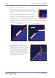
Table Of Contents
- Contents
- Overview
- Chapter 1: Introduction
- Chapter 2: PRO2 Live Audio System
- Chapter 3: About The PRO2 Control Centre
- Getting Started
- Basic Operation Of The PRO2
- Chapter 5: Before You Start
- Chapter 6: Working With The PRO2 Control Centre
- Chapter 7: Navigation
- Chapter 8: Patching
- Introduction
- Terms used in PRO2 patching
- About the Patching screen
- Patching tooltips
- About the patching procedure
- Configuring the devices
- Setting up the I/O rack device(s)
- How to patch
- Chapter 9: Basic Operation
- Setting a mic amplifier’s input gain
- Setting the high and low pass filters
- Input equalisation (E zone)
- Input dynamics processing (D zone)
- Output processing
- Using VCA/POPulation groups
- Setting up a mix
- Setting up the effects rack
- Simple routing to master stereo outputs
- Automation
- Configuring the inputs and outputs
- Using copy and paste
- User library (presets)
- Surround panning
- Area B operation
- Saving your show files to a USB memory stick
- External AES50 synchronisation
- Security (locking mode)
- Advanced Operation And Features
- Chapter 10: Stereo Linking
- Chapter 11: Panning
- Chapter 12: Soloing
- Chapter 13: Muting
- Chapter 14: Monitors And Communications
- Chapter 15: Graphic Equaliser (GEQ)
- Chapter 16: Internal Effects
- Chapter 17: Control Groups
- Chapter 18: Copy And Paste
- Chapter 19: Assignable Controls
- Chapter 20: Scenes And Shows (Automation)
- About automation
- Automation controls
- Automation screen
- Using the right-click menu
- Scenes
- Scene contents
- Point scenes
- Numbering and navigation
- Initial snapshot scene (scene 0)
- Date and time
- Scene cue list
- Editing scene properties
- Adding a new scene
- Copying and deleting scenes
- Changing the order of the scenes
- Overriding store scope
- Using patching in automation
- Using zoom
- Show files
- Rehearsals
- Safes
- Chapter 21: Scope (Automation)
- Chapter 22: Events (Automation)
- Chapter 23: Crossfades (Automation)
- Chapter 24: User Libraries (Presets)
- Chapter 25: File Management
- Chapter 26: Using Other Devices With The PRO2
- Chapter 27: Changing The Preferences
- Setting the meter preferences
- Configuring a virtual soundcheck
- Configuring playback
- Restoring the PRO2 defaults
- Checking the build information
- Using patching in automation
- Selecting the surround mode
- Setting the time and date
- Setting the user interface preferences
- Setting the navigation mode
- VCA unfolding
- Changing the default input/output names
- On-scene store
- Changing the signal processing preferences
- Adjusting PRO2 illumination
- Selecting the function of the foot switch(es)
- Selecting the fan speed
- Remote control server
- Configuring the channels, groups and internal units
- Chapter 28: Delay Compensation (Latency)
- Description
- Chapter 29: Panel Connections
- Chapter 30: Input Channels
- Chapter 31: Output Channels
- Chapter 32: GUI Menu
- Appendices
- Appendix A: Application Notes
- Appendix B: Functional Block Diagrams
- Appendix C: Technical Specification
- PRO2 general statistics
- PRO2 general specifications
- PRO2 audio performance specifications
- PRO2 system inputs and outputs
- DL251 I/O box - analogue inputs
- DL251 I/O box - analogue outputs
- DL251 I/O box - MIDI
- DL251 I/O box - digital system inputs and outputs
- PRO2 control surface - DSP/router system inputs and outputs
- PRO2 control surface - analogue audio system inputs
- PRO2 control surface - analogue audio system outputs
- PRO2 control surface - digital audio system inputs and outputs
- PRO2 control surface - control data system inputs and outputs
- PRO2 control centre - miscellaneous inputs and outputs
- Inputs and output characteristics
- Main processing functions
- Status functions
- Appendix D: Troubleshooting
- Appendix E: Updating The PRO2 Host Software
- Appendix F: Parameters Affected By Scope
- Appendix G: Parameters Affected By Automate Patching
- Appendix H: Parameters Protected By Safes
- Appendix I: Parameters Affected By Copy And Paste
- Appendix J: Parameters Affected By Stereo Linking
- Appendix K: Parameters Copied Through Scenes
- Appendix L: Service Information
- Glossary
- Other important information
- 1 Register online. Please register your new Midas equipment right after you purchase it by visiting www.midasconsoles.com. Registering your purchase using our simple online form helps us to process your repair claims more quickly and efficiently. Als...
- 2 Malfunction. Should your MUSIC Group Authorized Reseller not be located in your vicinity, you may contact the MUSIC Group Authorized Fulfiller for your country at www.midasconsoles.com. If your country is not listed please contact the “United Kin...
- 3 Power Connections. Before plugging the unit into a power socket, please make sure you are using the correct mains voltage for your particular model. Faulty fuses must be replaced with fuses of the same type and rating without exception.
- FEDERAL COMMUNICATIONS COMMISSION COMPLIANCE INFORMATION

246 Chapter 30: Input Channels
PRO2 Live Audio System
Owner’s Manual
5 SLOPE switch
(digital trim only)
Selects the low pass filter. Where, switch on
(illuminated) = 12dB slope and switch off = 6dB
slope.
6 stage box control
knob
Adjusts the input gain of the remote amplifier in 5dB
steps, ranging from -5dB to +40dB. Note that the
stage box control knob on the control surface will
only adjust the gain currently selected to the GUI
input channel strip, that is, stage box or digital trim.
7 CHECK switch
(stage box only)
Monitors the mic amp input after the 30Hz filter, but
before any further processing. (The 30Hz subsonic
filter switch accesses the high pass filter on DL431
Mic Splitter when connected to a PRO2. In this case,
the gain steps would be 2.5dB from -2.5dB to
+45dB.)
8 30Hz subsonic
filter switch
Acts on remote amplifier (mic splitter) to remove very
low frequencies in the audio signal — usually caused
by noise on stage. This avoids wasting valuable
headroom trying to digitise it.
9 low pass control
knob (digital trim
only)
Adjusts frequency of low pass filter in the range 2kHz
to 20kHz.
10 Low pass filter
switch /[IN]
(digital trim only)
Activates low pass filter in the input channel signal
path before the insert points and EQ.
11 High pass filter
switch /[IN]
(digital trim only)
Activates high pass filter in the input channel signal
path before the insert points and EQ.
12 high pass control
knob (digital trim
only)
Adjusts frequency of high pass filter in the range
10Hz to 400Hz.
13
Phase switch
Applies a 180° inversion of the input signal polarity
within the input amplifier, such that channel signal
will have opposite polarity to the input signal.
This is used to correct input signal phase problems
when trying to sum signals that are 180° out of
phase. For example, where two mics are facing each
other when using a mic on both the top and bottom of
a snare drum. Ordinarily, the two mics would be out
of phase - causing cancellation when the control
centre sums the two signals into the output.
Reversing the phase of one signal causes the mics to
have the same phase, thus avoiding cancellation.
14 Gain trim (digital
trim) control knob
Applies continuous trim adjustment (small digital
steps) of the input signal level in the range –40dB to
+20dB. Gives a further 60dB of fine adjustment
(DSP) on top of the remote amplifier gain setting.
This control knob on the input fast strips can be
controlling stage box gain, digital trim or delay,
depending on the current state of the swap.
15 Graph Shows the effects of currently applied filter.
Item Control Function