
Operator Manual
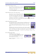


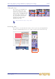
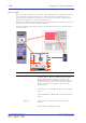


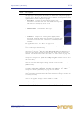
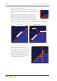
Table Of Contents
- Contents
- Overview
- Chapter 1: Introduction
- Chapter 2: PRO2 Live Audio System
- Chapter 3: About The PRO2 Control Centre
- Getting Started
- Basic Operation Of The PRO2
- Chapter 5: Before You Start
- Chapter 6: Working With The PRO2 Control Centre
- Chapter 7: Navigation
- Chapter 8: Patching
- Introduction
- Terms used in PRO2 patching
- About the Patching screen
- Patching tooltips
- About the patching procedure
- Configuring the devices
- Setting up the I/O rack device(s)
- How to patch
- Chapter 9: Basic Operation
- Setting a mic amplifier’s input gain
- Setting the high and low pass filters
- Input equalisation (E zone)
- Input dynamics processing (D zone)
- Output processing
- Using VCA/POPulation groups
- Setting up a mix
- Setting up the effects rack
- Simple routing to master stereo outputs
- Automation
- Configuring the inputs and outputs
- Using copy and paste
- User library (presets)
- Surround panning
- Area B operation
- Saving your show files to a USB memory stick
- External AES50 synchronisation
- Security (locking mode)
- Advanced Operation And Features
- Chapter 10: Stereo Linking
- Chapter 11: Panning
- Chapter 12: Soloing
- Chapter 13: Muting
- Chapter 14: Monitors And Communications
- Chapter 15: Graphic Equaliser (GEQ)
- Chapter 16: Internal Effects
- Chapter 17: Control Groups
- Chapter 18: Copy And Paste
- Chapter 19: Assignable Controls
- Chapter 20: Scenes And Shows (Automation)
- About automation
- Automation controls
- Automation screen
- Using the right-click menu
- Scenes
- Scene contents
- Point scenes
- Numbering and navigation
- Initial snapshot scene (scene 0)
- Date and time
- Scene cue list
- Editing scene properties
- Adding a new scene
- Copying and deleting scenes
- Changing the order of the scenes
- Overriding store scope
- Using patching in automation
- Using zoom
- Show files
- Rehearsals
- Safes
- Chapter 21: Scope (Automation)
- Chapter 22: Events (Automation)
- Chapter 23: Crossfades (Automation)
- Chapter 24: User Libraries (Presets)
- Chapter 25: File Management
- Chapter 26: Using Other Devices With The PRO2
- Chapter 27: Changing The Preferences
- Setting the meter preferences
- Configuring a virtual soundcheck
- Configuring playback
- Restoring the PRO2 defaults
- Checking the build information
- Using patching in automation
- Selecting the surround mode
- Setting the time and date
- Setting the user interface preferences
- Setting the navigation mode
- VCA unfolding
- Changing the default input/output names
- On-scene store
- Changing the signal processing preferences
- Adjusting PRO2 illumination
- Selecting the function of the foot switch(es)
- Selecting the fan speed
- Remote control server
- Configuring the channels, groups and internal units
- Chapter 28: Delay Compensation (Latency)
- Description
- Chapter 29: Panel Connections
- Chapter 30: Input Channels
- Chapter 31: Output Channels
- Chapter 32: GUI Menu
- Appendices
- Appendix A: Application Notes
- Appendix B: Functional Block Diagrams
- Appendix C: Technical Specification
- PRO2 general statistics
- PRO2 general specifications
- PRO2 audio performance specifications
- PRO2 system inputs and outputs
- DL251 I/O box - analogue inputs
- DL251 I/O box - analogue outputs
- DL251 I/O box - MIDI
- DL251 I/O box - digital system inputs and outputs
- PRO2 control surface - DSP/router system inputs and outputs
- PRO2 control surface - analogue audio system inputs
- PRO2 control surface - analogue audio system outputs
- PRO2 control surface - digital audio system inputs and outputs
- PRO2 control surface - control data system inputs and outputs
- PRO2 control centre - miscellaneous inputs and outputs
- Inputs and output characteristics
- Main processing functions
- Status functions
- Appendix D: Troubleshooting
- Appendix E: Updating The PRO2 Host Software
- Appendix F: Parameters Affected By Scope
- Appendix G: Parameters Affected By Automate Patching
- Appendix H: Parameters Protected By Safes
- Appendix I: Parameters Affected By Copy And Paste
- Appendix J: Parameters Affected By Stereo Linking
- Appendix K: Parameters Copied Through Scenes
- Appendix L: Service Information
- Glossary
- Other important information
- 1 Register online. Please register your new Midas equipment right after you purchase it by visiting www.midasconsoles.com. Registering your purchase using our simple online form helps us to process your repair claims more quickly and efficiently. Als...
- 2 Malfunction. Should your MUSIC Group Authorized Reseller not be located in your vicinity, you may contact the MUSIC Group Authorized Fulfiller for your country at www.midasconsoles.com. If your country is not listed please contact the “United Kin...
- 3 Power Connections. Before plugging the unit into a power socket, please make sure you are using the correct mains voltage for your particular model. Faulty fuses must be replaced with fuses of the same type and rating without exception.
- FEDERAL COMMUNICATIONS COMMISSION COMPLIANCE INFORMATION

Channel configuration controls 243
PRO2 Live Audio System
Owner’s Manual
Input channel ID (GUI only)
You can change the channel name via the GUI,
which can be done directly in the input channel
overview or in any of the detail areas (see
“Text editing” on page 42).
To change the background colour of the input channel name field (default is green),
open the Naming Sheet screen of the GUI menu.
Input channel source select (GUI only)
The channel’s source is shown in the text field;
if none has been selected, it will contain the text
“Unassigned” (as shown right). You can select
the source for this channel by clicking source,
which opens the Patching screen (see Chapter
8 "Patching" on page 47). Also, by clicking the recorder button you can set the
input source to tape returns to obtain an alternative input, for example, from a hard
disk recorder for a virtual soundcheck.
Input channel delay (GUI only)
The input channel delay can only be changed via the delay section of
the configuration detail area (GUI channel strip). This section has a
control knob for adjusting the delay in the range 0ms to 50ms; this
value is displayed in both milliseconds (ms) and metres. You can fine
tune the delay value using the spin buttons to the left of the control
knob.
The delay section allows you to incorporate a time delay on an input
channel, which is used mainly for mic placements and time aligning to
reduce comb filtering. For example, on a drum kit mic set up, you may have a mic
close to a snare drum and a couple of overhead mics. In this case, setting an input
channel delay on the snare drum — to bring it more in line with the overheads — will
probably produce a better sound.
Stereo linking (GUI only)
The linking/gain swap section of the
configuration detail has a LINK OPT. button that
opens a Stereo Linking Options window from
where you can choose which parameters you
want to link between the pair.
For more information, see Chapter 10 "Stereo
Linking" on page 95.