
Operator Manual


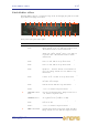


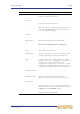

Table Of Contents
- Contents
- Overview
- Chapter 1: Introduction
- Chapter 2: PRO2 Live Audio System
- Chapter 3: About The PRO2 Control Centre
- Getting Started
- Basic Operation Of The PRO2
- Chapter 5: Before You Start
- Chapter 6: Working With The PRO2 Control Centre
- Chapter 7: Navigation
- Chapter 8: Patching
- Introduction
- Terms used in PRO2 patching
- About the Patching screen
- Patching tooltips
- About the patching procedure
- Configuring the devices
- Setting up the I/O rack device(s)
- How to patch
- Chapter 9: Basic Operation
- Setting a mic amplifier’s input gain
- Setting the high and low pass filters
- Input equalisation (E zone)
- Input dynamics processing (D zone)
- Output processing
- Using VCA/POPulation groups
- Setting up a mix
- Setting up the effects rack
- Simple routing to master stereo outputs
- Automation
- Configuring the inputs and outputs
- Using copy and paste
- User library (presets)
- Surround panning
- Area B operation
- Saving your show files to a USB memory stick
- External AES50 synchronisation
- Security (locking mode)
- Advanced Operation And Features
- Chapter 10: Stereo Linking
- Chapter 11: Panning
- Chapter 12: Soloing
- Chapter 13: Muting
- Chapter 14: Monitors And Communications
- Chapter 15: Graphic Equaliser (GEQ)
- Chapter 16: Internal Effects
- Chapter 17: Control Groups
- Chapter 18: Copy And Paste
- Chapter 19: Assignable Controls
- Chapter 20: Scenes And Shows (Automation)
- About automation
- Automation controls
- Automation screen
- Using the right-click menu
- Scenes
- Scene contents
- Point scenes
- Numbering and navigation
- Initial snapshot scene (scene 0)
- Date and time
- Scene cue list
- Editing scene properties
- Adding a new scene
- Copying and deleting scenes
- Changing the order of the scenes
- Overriding store scope
- Using patching in automation
- Using zoom
- Show files
- Rehearsals
- Safes
- Chapter 21: Scope (Automation)
- Chapter 22: Events (Automation)
- Chapter 23: Crossfades (Automation)
- Chapter 24: User Libraries (Presets)
- Chapter 25: File Management
- Chapter 26: Using Other Devices With The PRO2
- Chapter 27: Changing The Preferences
- Setting the meter preferences
- Configuring a virtual soundcheck
- Configuring playback
- Restoring the PRO2 defaults
- Checking the build information
- Using patching in automation
- Selecting the surround mode
- Setting the time and date
- Setting the user interface preferences
- Setting the navigation mode
- VCA unfolding
- Changing the default input/output names
- On-scene store
- Changing the signal processing preferences
- Adjusting PRO2 illumination
- Selecting the function of the foot switch(es)
- Selecting the fan speed
- Remote control server
- Configuring the channels, groups and internal units
- Chapter 28: Delay Compensation (Latency)
- Description
- Chapter 29: Panel Connections
- Chapter 30: Input Channels
- Chapter 31: Output Channels
- Chapter 32: GUI Menu
- Appendices
- Appendix A: Application Notes
- Appendix B: Functional Block Diagrams
- Appendix C: Technical Specification
- PRO2 general statistics
- PRO2 general specifications
- PRO2 audio performance specifications
- PRO2 system inputs and outputs
- DL251 I/O box - analogue inputs
- DL251 I/O box - analogue outputs
- DL251 I/O box - MIDI
- DL251 I/O box - digital system inputs and outputs
- PRO2 control surface - DSP/router system inputs and outputs
- PRO2 control surface - analogue audio system inputs
- PRO2 control surface - analogue audio system outputs
- PRO2 control surface - digital audio system inputs and outputs
- PRO2 control surface - control data system inputs and outputs
- PRO2 control centre - miscellaneous inputs and outputs
- Inputs and output characteristics
- Main processing functions
- Status functions
- Appendix D: Troubleshooting
- Appendix E: Updating The PRO2 Host Software
- Appendix F: Parameters Affected By Scope
- Appendix G: Parameters Affected By Automate Patching
- Appendix H: Parameters Protected By Safes
- Appendix I: Parameters Affected By Copy And Paste
- Appendix J: Parameters Affected By Stereo Linking
- Appendix K: Parameters Copied Through Scenes
- Appendix L: Service Information
- Glossary
- Other important information
- 1 Register online. Please register your new Midas equipment right after you purchase it by visiting www.midasconsoles.com. Registering your purchase using our simple online form helps us to process your repair claims more quickly and efficiently. Als...
- 2 Malfunction. Should your MUSIC Group Authorized Reseller not be located in your vicinity, you may contact the MUSIC Group Authorized Fulfiller for your country at www.midasconsoles.com. If your country is not listed please contact the “United Kin...
- 3 Power Connections. Before plugging the unit into a power socket, please make sure you are using the correct mains voltage for your particular model. Faulty fuses must be replaced with fuses of the same type and rating without exception.
- FEDERAL COMMUNICATIONS COMMISSION COMPLIANCE INFORMATION

Pitch Shifter effect 137
PRO2 Live Audio System
Owner’s Manual
Pitch Shifter effect
The Pitch Shifter effect is a sound processing device for changing the pitch of an audio
signal without changing its duration.
Front panel of the pitch shifter effect
Item Control Function
1 COARSE control
knob
Adjusts the pitch shifting amount in whole tones.
Range is from -12 to +12, with 0 at top dead centre.
The numerical value is shown underneath.
2 FINE control knob Fine tunes the pitch shifting in 1% increments of a
whole tone. Range is from -100 to +100, with 0 at
top dead centre. The numerical value is shown
underneath.
3 PREDELAY control
knob
Sets the delay time before the pitch shift. Range is
from 1 to 500, with 22 at top dead centre.
4 FB DELAY control
knob
Sets the delay time on the feedback loop. Range is
from 1 to 500, with 22 at top dead centre.
5 FEEDBACK control
knob
Sets the amount of feedback (output fed back to
input) in %. For more details, see “Feedback” on
page 138. Range is from 0 to 100, with 50 at top
dead centre.
6 LEVEL control
knob
Sets the output level of the individual channel. Range
is from -40 to -10, with -20 at top dead centre.
7 PAN control knob Adjusts the position of the individual channel signal in
the unit's stereo output.
8 HF DAMP control
knob
Adjusts the HF attenuation of delay repeats. Range is
from 2k to 20k, with 6k at top dead centre.
9 HI EQ control
knob
Boosts/attenuates high frequencies. Range is from
-12 to +12, with 0 at top dead centre.
10 OUT LVL control
knob
Sets the overall output level. Range is from -20 to
+20, with 0 at top dead centre.
11 INPUT and
OUTPUT meters
Shows the input/output signal levels on dual
20-segment meters (-36dB to +21dB).
12 LF DAMP control
knob
Adjusts the LF attenuation of delay repeats. Range is
from 20 to 400.
13 LO EQ control
knob
Boosts/attenuates low frequencies. Range is from
-12 to +12, with 0 at top dead centre.
14 MIX control knob Controls the balance between dry signal and effect.
Range is from 0 to 100, with 50 at top dead centre.
1 2 3 4 5 6 7 8 9 10 11
151413127654321
16