
Operator Manual
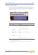


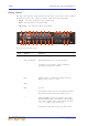

Table Of Contents
- Contents
- Overview
- Chapter 1: Introduction
- Chapter 2: PRO2 Live Audio System
- Chapter 3: About The PRO2 Control Centre
- Getting Started
- Basic Operation Of The PRO2
- Chapter 5: Before You Start
- Chapter 6: Working With The PRO2 Control Centre
- Chapter 7: Navigation
- Chapter 8: Patching
- Introduction
- Terms used in PRO2 patching
- About the Patching screen
- Patching tooltips
- About the patching procedure
- Configuring the devices
- Setting up the I/O rack device(s)
- How to patch
- Chapter 9: Basic Operation
- Setting a mic amplifier’s input gain
- Setting the high and low pass filters
- Input equalisation (E zone)
- Input dynamics processing (D zone)
- Output processing
- Using VCA/POPulation groups
- Setting up a mix
- Setting up the effects rack
- Simple routing to master stereo outputs
- Automation
- Configuring the inputs and outputs
- Using copy and paste
- User library (presets)
- Surround panning
- Area B operation
- Saving your show files to a USB memory stick
- External AES50 synchronisation
- Security (locking mode)
- Advanced Operation And Features
- Chapter 10: Stereo Linking
- Chapter 11: Panning
- Chapter 12: Soloing
- Chapter 13: Muting
- Chapter 14: Monitors And Communications
- Chapter 15: Graphic Equaliser (GEQ)
- Chapter 16: Internal Effects
- Chapter 17: Control Groups
- Chapter 18: Copy And Paste
- Chapter 19: Assignable Controls
- Chapter 20: Scenes And Shows (Automation)
- About automation
- Automation controls
- Automation screen
- Using the right-click menu
- Scenes
- Scene contents
- Point scenes
- Numbering and navigation
- Initial snapshot scene (scene 0)
- Date and time
- Scene cue list
- Editing scene properties
- Adding a new scene
- Copying and deleting scenes
- Changing the order of the scenes
- Overriding store scope
- Using patching in automation
- Using zoom
- Show files
- Rehearsals
- Safes
- Chapter 21: Scope (Automation)
- Chapter 22: Events (Automation)
- Chapter 23: Crossfades (Automation)
- Chapter 24: User Libraries (Presets)
- Chapter 25: File Management
- Chapter 26: Using Other Devices With The PRO2
- Chapter 27: Changing The Preferences
- Setting the meter preferences
- Configuring a virtual soundcheck
- Configuring playback
- Restoring the PRO2 defaults
- Checking the build information
- Using patching in automation
- Selecting the surround mode
- Setting the time and date
- Setting the user interface preferences
- Setting the navigation mode
- VCA unfolding
- Changing the default input/output names
- On-scene store
- Changing the signal processing preferences
- Adjusting PRO2 illumination
- Selecting the function of the foot switch(es)
- Selecting the fan speed
- Remote control server
- Configuring the channels, groups and internal units
- Chapter 28: Delay Compensation (Latency)
- Description
- Chapter 29: Panel Connections
- Chapter 30: Input Channels
- Chapter 31: Output Channels
- Chapter 32: GUI Menu
- Appendices
- Appendix A: Application Notes
- Appendix B: Functional Block Diagrams
- Appendix C: Technical Specification
- PRO2 general statistics
- PRO2 general specifications
- PRO2 audio performance specifications
- PRO2 system inputs and outputs
- DL251 I/O box - analogue inputs
- DL251 I/O box - analogue outputs
- DL251 I/O box - MIDI
- DL251 I/O box - digital system inputs and outputs
- PRO2 control surface - DSP/router system inputs and outputs
- PRO2 control surface - analogue audio system inputs
- PRO2 control surface - analogue audio system outputs
- PRO2 control surface - digital audio system inputs and outputs
- PRO2 control surface - control data system inputs and outputs
- PRO2 control centre - miscellaneous inputs and outputs
- Inputs and output characteristics
- Main processing functions
- Status functions
- Appendix D: Troubleshooting
- Appendix E: Updating The PRO2 Host Software
- Appendix F: Parameters Affected By Scope
- Appendix G: Parameters Affected By Automate Patching
- Appendix H: Parameters Protected By Safes
- Appendix I: Parameters Affected By Copy And Paste
- Appendix J: Parameters Affected By Stereo Linking
- Appendix K: Parameters Copied Through Scenes
- Appendix L: Service Information
- Glossary
- Other important information
- 1 Register online. Please register your new Midas equipment right after you purchase it by visiting www.midasconsoles.com. Registering your purchase using our simple online form helps us to process your repair claims more quickly and efficiently. Als...
- 2 Malfunction. Should your MUSIC Group Authorized Reseller not be located in your vicinity, you may contact the MUSIC Group Authorized Fulfiller for your country at www.midasconsoles.com. If your country is not listed please contact the “United Kin...
- 3 Power Connections. Before plugging the unit into a power socket, please make sure you are using the correct mains voltage for your particular model. Faulty fuses must be replaced with fuses of the same type and rating without exception.
- FEDERAL COMMUNICATIONS COMMISSION COMPLIANCE INFORMATION

132 Chapter 16: Internal Effects
PRO2 Live Audio System
Owner’s Manual
Virtual DN780 Reverb effect
The Virtual DN780 Reverb provides emulation of the vintage Klark Teknik DN780 Digital
Reverberator/Processor unit. The DN780 is not just a reverberation device, it also gives
the user a unique and flexible means of producing realistic acoustic simulations for
environments of all types and sizes. The provision of effects programs further extends
this versatility, making it a very powerful acoustic processing package.
Front panel of the reverb effect
Item Control Function
1 LF (low frequency)
control knob
REVERBERATION section control that adjusts the
decay time at the low end of the reverb spectrum.
Range is from -7 to +7.
2 HF (high
frequency) control
knob
REVERBERATION section control that adjusts the
decay time at the high end of the reverb spectrum,
which sets the absorption characteristic of the
simulated space. Range is from -7 to +7.
3 ROOMSIZE
control knob
Adjusts the average dimension of the simulated
space. Range is from 8 to 90 metres. A momentary
mute is implemented when this control is adjusted.
4 DECAY control
knob
REVERBERATION section control that sets the
overall (mid-band) reverberation decay time. Range
is from 0.1 to 18 seconds, depending on room size.
5 LEVEL control
knob
REFLECTIONS section control that acts as a ‘depth’
control by altering the apparent distance between the
sound source and the listener. Alternatively, adjusts
the input level for Sound-On-Sound/Infinite
Room. Range is from 0 to 9.
6 PATTERN control
knob
REFLECTIONS section control that controls the
‘density’ of early reflections. Selects the number and
spacing of Early Reflections/ADT/Multi-tap delays.
Range is from 1 to 9.
7 PRE DELAY
control knob
Controls the amount of delay (in milliseconds)
between the initial signal and the onset of
reverberation. On certain program types, pre-delay
is inserted between early reflections and reverb to
improve authenticity. Its range is algorithm
dependent.
Low level, phase-dependent ‘clicks’ are produced
when pre-delay is altered during the program.
8 List of algorithms
and algorithm
select button
These algorithms emulate the ones on the original
DN780. Use the select button to scroll through the
list to select the one you want.
13 11 9 10
1232145671516
14
8