
Operator Manual
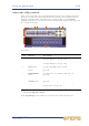

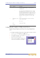


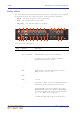
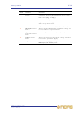

Table Of Contents
- Contents
- Overview
- Chapter 1: Introduction
- Chapter 2: PRO2 Live Audio System
- Chapter 3: About The PRO2 Control Centre
- Getting Started
- Basic Operation Of The PRO2
- Chapter 5: Before You Start
- Chapter 6: Working With The PRO2 Control Centre
- Chapter 7: Navigation
- Chapter 8: Patching
- Introduction
- Terms used in PRO2 patching
- About the Patching screen
- Patching tooltips
- About the patching procedure
- Configuring the devices
- Setting up the I/O rack device(s)
- How to patch
- Chapter 9: Basic Operation
- Setting a mic amplifier’s input gain
- Setting the high and low pass filters
- Input equalisation (E zone)
- Input dynamics processing (D zone)
- Output processing
- Using VCA/POPulation groups
- Setting up a mix
- Setting up the effects rack
- Simple routing to master stereo outputs
- Automation
- Configuring the inputs and outputs
- Using copy and paste
- User library (presets)
- Surround panning
- Area B operation
- Saving your show files to a USB memory stick
- External AES50 synchronisation
- Security (locking mode)
- Advanced Operation And Features
- Chapter 10: Stereo Linking
- Chapter 11: Panning
- Chapter 12: Soloing
- Chapter 13: Muting
- Chapter 14: Monitors And Communications
- Chapter 15: Graphic Equaliser (GEQ)
- Chapter 16: Internal Effects
- Chapter 17: Control Groups
- Chapter 18: Copy And Paste
- Chapter 19: Assignable Controls
- Chapter 20: Scenes And Shows (Automation)
- About automation
- Automation controls
- Automation screen
- Using the right-click menu
- Scenes
- Scene contents
- Point scenes
- Numbering and navigation
- Initial snapshot scene (scene 0)
- Date and time
- Scene cue list
- Editing scene properties
- Adding a new scene
- Copying and deleting scenes
- Changing the order of the scenes
- Overriding store scope
- Using patching in automation
- Using zoom
- Show files
- Rehearsals
- Safes
- Chapter 21: Scope (Automation)
- Chapter 22: Events (Automation)
- Chapter 23: Crossfades (Automation)
- Chapter 24: User Libraries (Presets)
- Chapter 25: File Management
- Chapter 26: Using Other Devices With The PRO2
- Chapter 27: Changing The Preferences
- Setting the meter preferences
- Configuring a virtual soundcheck
- Configuring playback
- Restoring the PRO2 defaults
- Checking the build information
- Using patching in automation
- Selecting the surround mode
- Setting the time and date
- Setting the user interface preferences
- Setting the navigation mode
- VCA unfolding
- Changing the default input/output names
- On-scene store
- Changing the signal processing preferences
- Adjusting PRO2 illumination
- Selecting the function of the foot switch(es)
- Selecting the fan speed
- Remote control server
- Configuring the channels, groups and internal units
- Chapter 28: Delay Compensation (Latency)
- Description
- Chapter 29: Panel Connections
- Chapter 30: Input Channels
- Chapter 31: Output Channels
- Chapter 32: GUI Menu
- Appendices
- Appendix A: Application Notes
- Appendix B: Functional Block Diagrams
- Appendix C: Technical Specification
- PRO2 general statistics
- PRO2 general specifications
- PRO2 audio performance specifications
- PRO2 system inputs and outputs
- DL251 I/O box - analogue inputs
- DL251 I/O box - analogue outputs
- DL251 I/O box - MIDI
- DL251 I/O box - digital system inputs and outputs
- PRO2 control surface - DSP/router system inputs and outputs
- PRO2 control surface - analogue audio system inputs
- PRO2 control surface - analogue audio system outputs
- PRO2 control surface - digital audio system inputs and outputs
- PRO2 control surface - control data system inputs and outputs
- PRO2 control centre - miscellaneous inputs and outputs
- Inputs and output characteristics
- Main processing functions
- Status functions
- Appendix D: Troubleshooting
- Appendix E: Updating The PRO2 Host Software
- Appendix F: Parameters Affected By Scope
- Appendix G: Parameters Affected By Automate Patching
- Appendix H: Parameters Protected By Safes
- Appendix I: Parameters Affected By Copy And Paste
- Appendix J: Parameters Affected By Stereo Linking
- Appendix K: Parameters Copied Through Scenes
- Appendix L: Service Information
- Glossary
- Other important information
- 1 Register online. Please register your new Midas equipment right after you purchase it by visiting www.midasconsoles.com. Registering your purchase using our simple online form helps us to process your repair claims more quickly and efficiently. Als...
- 2 Malfunction. Should your MUSIC Group Authorized Reseller not be located in your vicinity, you may contact the MUSIC Group Authorized Fulfiller for your country at www.midasconsoles.com. If your country is not listed please contact the “United Kin...
- 3 Power Connections. Before plugging the unit into a power socket, please make sure you are using the correct mains voltage for your particular model. Faulty fuses must be replaced with fuses of the same type and rating without exception.
- FEDERAL COMMUNICATIONS COMMISSION COMPLIANCE INFORMATION

124 Chapter 15: Graphic Equaliser (GEQ)
PRO2 Live Audio System
Owner’s Manual
>> To patch a source to a GEQ
1 Open the window of the GEQ.
2 Open the GEQ source drop-down list. (An unpatched GEQ will have “None”
displayed in the text field.)
3 In the drop-down list, click the source
you want. For example, “Aux Send
3”. The new patching assignment will
appear in the source name field (as
shown right) and in the border on the
left of GEQ panel.
4 Click CLOSE to accept the change
and close the GEQ’s window.
The new GEQ patching source assignment
will appear in the virtual rack.
GEQ front panel features
The front panel of the GEQ, as displayed on the GUI, represents the Klark Teknik DN370
Graphic Equaliser. It includes a graphic EQ (faders) section and a filters section.
Thirty one faders provide fine adjustment of each frequency band. The 31 frequency
bands are spaced 1/3 octave apart on the standard ISO 266 frequency centres. All the
functions of the GEQ can be bypassed via an EQ switch, such that the output will be the
same as the input.
The GEQ has one high pass filter, one low pass filter and two variable frequency notch
filters. Each filter is adjusted via a control knob on the GUI screen. To audition the
effect of the filters, use either the EQ switch (which will also bypass the GEQ) or the
individual filter switch.
GEQ front panel
Item Control Function
1 Fader (31-off). Adjusts signal level.
2 SLOPE button Switches the high or low pass filter between 6dB and
12dB. Adjacent yellow LEDs indicate the active
mode.
3 High pass filter
control knob
Adjusts the cut off frequency, which is continuously
variable from 20Hz to 500Hz.
4 Low pass filter
control knob
Adjusts the cut off frequency, which is continuously
variable from 2kHz to 20kHz.
3
1 3 42 56
7891011