
Operator Manual

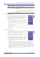


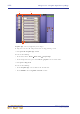
Table Of Contents
- Contents
- Overview
- Chapter 1: Introduction
- Chapter 2: PRO2 Live Audio System
- Chapter 3: About The PRO2 Control Centre
- Getting Started
- Basic Operation Of The PRO2
- Chapter 5: Before You Start
- Chapter 6: Working With The PRO2 Control Centre
- Chapter 7: Navigation
- Chapter 8: Patching
- Introduction
- Terms used in PRO2 patching
- About the Patching screen
- Patching tooltips
- About the patching procedure
- Configuring the devices
- Setting up the I/O rack device(s)
- How to patch
- Chapter 9: Basic Operation
- Setting a mic amplifier’s input gain
- Setting the high and low pass filters
- Input equalisation (E zone)
- Input dynamics processing (D zone)
- Output processing
- Using VCA/POPulation groups
- Setting up a mix
- Setting up the effects rack
- Simple routing to master stereo outputs
- Automation
- Configuring the inputs and outputs
- Using copy and paste
- User library (presets)
- Surround panning
- Area B operation
- Saving your show files to a USB memory stick
- External AES50 synchronisation
- Security (locking mode)
- Advanced Operation And Features
- Chapter 10: Stereo Linking
- Chapter 11: Panning
- Chapter 12: Soloing
- Chapter 13: Muting
- Chapter 14: Monitors And Communications
- Chapter 15: Graphic Equaliser (GEQ)
- Chapter 16: Internal Effects
- Chapter 17: Control Groups
- Chapter 18: Copy And Paste
- Chapter 19: Assignable Controls
- Chapter 20: Scenes And Shows (Automation)
- About automation
- Automation controls
- Automation screen
- Using the right-click menu
- Scenes
- Scene contents
- Point scenes
- Numbering and navigation
- Initial snapshot scene (scene 0)
- Date and time
- Scene cue list
- Editing scene properties
- Adding a new scene
- Copying and deleting scenes
- Changing the order of the scenes
- Overriding store scope
- Using patching in automation
- Using zoom
- Show files
- Rehearsals
- Safes
- Chapter 21: Scope (Automation)
- Chapter 22: Events (Automation)
- Chapter 23: Crossfades (Automation)
- Chapter 24: User Libraries (Presets)
- Chapter 25: File Management
- Chapter 26: Using Other Devices With The PRO2
- Chapter 27: Changing The Preferences
- Setting the meter preferences
- Configuring a virtual soundcheck
- Configuring playback
- Restoring the PRO2 defaults
- Checking the build information
- Using patching in automation
- Selecting the surround mode
- Setting the time and date
- Setting the user interface preferences
- Setting the navigation mode
- VCA unfolding
- Changing the default input/output names
- On-scene store
- Changing the signal processing preferences
- Adjusting PRO2 illumination
- Selecting the function of the foot switch(es)
- Selecting the fan speed
- Remote control server
- Configuring the channels, groups and internal units
- Chapter 28: Delay Compensation (Latency)
- Description
- Chapter 29: Panel Connections
- Chapter 30: Input Channels
- Chapter 31: Output Channels
- Chapter 32: GUI Menu
- Appendices
- Appendix A: Application Notes
- Appendix B: Functional Block Diagrams
- Appendix C: Technical Specification
- PRO2 general statistics
- PRO2 general specifications
- PRO2 audio performance specifications
- PRO2 system inputs and outputs
- DL251 I/O box - analogue inputs
- DL251 I/O box - analogue outputs
- DL251 I/O box - MIDI
- DL251 I/O box - digital system inputs and outputs
- PRO2 control surface - DSP/router system inputs and outputs
- PRO2 control surface - analogue audio system inputs
- PRO2 control surface - analogue audio system outputs
- PRO2 control surface - digital audio system inputs and outputs
- PRO2 control surface - control data system inputs and outputs
- PRO2 control centre - miscellaneous inputs and outputs
- Inputs and output characteristics
- Main processing functions
- Status functions
- Appendix D: Troubleshooting
- Appendix E: Updating The PRO2 Host Software
- Appendix F: Parameters Affected By Scope
- Appendix G: Parameters Affected By Automate Patching
- Appendix H: Parameters Protected By Safes
- Appendix I: Parameters Affected By Copy And Paste
- Appendix J: Parameters Affected By Stereo Linking
- Appendix K: Parameters Copied Through Scenes
- Appendix L: Service Information
- Glossary
- Other important information
- 1 Register online. Please register your new Midas equipment right after you purchase it by visiting www.midasconsoles.com. Registering your purchase using our simple online form helps us to process your repair claims more quickly and efficiently. Als...
- 2 Malfunction. Should your MUSIC Group Authorized Reseller not be located in your vicinity, you may contact the MUSIC Group Authorized Fulfiller for your country at www.midasconsoles.com. If your country is not listed please contact the “United Kin...
- 3 Power Connections. Before plugging the unit into a power socket, please make sure you are using the correct mains voltage for your particular model. Faulty fuses must be replaced with fuses of the same type and rating without exception.
- FEDERAL COMMUNICATIONS COMMISSION COMPLIANCE INFORMATION

Talk osc/routing 117
PRO2 Live Audio System
Owner’s Manual
Talk osc/routing
The talk / osc routing, or ‘internal talk groups’ section, sends signal generator and
talk mic signals to buses within the control centre. It contains four talk group switches
used for selecting the destination of the talk and OSC internal signals. The GUI has an
additional four configuration switches for programming.
Talk osc/routing controls on the control surface and GUI
Internal talk groups
You can assign talkback or send test signals to any audio bus on the control centre.
The preset ‘talk’ groups allow you to, for example, talk to groups of performers in a
monitor mix or make group announcements. Also, by using the internal tone oscillator,
you can perform signal path testing and equipment alignment.
There are four ‘talk’ groups available, which are operated via the GUI. The preset talk
groups let you can route to all inputs, all auxes, all matrices or all outputs.
Before you can select a talk group, the TALK/internal and/or OSC/internal buttons
must be switched on. (This also applies to generator routing.) Also, if any internal talk
or osc generator routing is active when the TALK/internal and/or OSC/internal
buttons are both switched off, this routing is cancelled.
When a talk group is activated, all talk group member functions are activated.
>> To activate a talk group
1 Make sure either one or both of the ‘internal’ buttons, that is, the TALK
(internal) button in the talk mic section and the OSC (internal) button in the
signal generator section, are on.
2 Click the desired talk/oscillator routing button.
Item Element Description
1 ALL switch Routes the talk/OSC internal signal to all outputs.
2 INP switch This input switch routes the talk/OSC internal signal
to the input section.
3 AUX switch Routes the talk/OSC internal signal to all auxes.
4 MTX switch This matrix talk switch routes the oscillator or talk
signal to the matrix outputs.
1
23
4