
Operator Manual

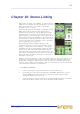
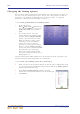
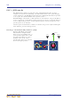
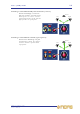


Table Of Contents
- Contents
- Overview
- Chapter 1: Introduction
- Chapter 2: PRO2 Live Audio System
- Chapter 3: About The PRO2 Control Centre
- Getting Started
- Basic Operation Of The PRO2
- Chapter 5: Before You Start
- Chapter 6: Working With The PRO2 Control Centre
- Chapter 7: Navigation
- Chapter 8: Patching
- Introduction
- Terms used in PRO2 patching
- About the Patching screen
- Patching tooltips
- About the patching procedure
- Configuring the devices
- Setting up the I/O rack device(s)
- How to patch
- Chapter 9: Basic Operation
- Setting a mic amplifier’s input gain
- Setting the high and low pass filters
- Input equalisation (E zone)
- Input dynamics processing (D zone)
- Output processing
- Using VCA/POPulation groups
- Setting up a mix
- Setting up the effects rack
- Simple routing to master stereo outputs
- Automation
- Configuring the inputs and outputs
- Using copy and paste
- User library (presets)
- Surround panning
- Area B operation
- Saving your show files to a USB memory stick
- External AES50 synchronisation
- Security (locking mode)
- Advanced Operation And Features
- Chapter 10: Stereo Linking
- Chapter 11: Panning
- Chapter 12: Soloing
- Chapter 13: Muting
- Chapter 14: Monitors And Communications
- Chapter 15: Graphic Equaliser (GEQ)
- Chapter 16: Internal Effects
- Chapter 17: Control Groups
- Chapter 18: Copy And Paste
- Chapter 19: Assignable Controls
- Chapter 20: Scenes And Shows (Automation)
- About automation
- Automation controls
- Automation screen
- Using the right-click menu
- Scenes
- Scene contents
- Point scenes
- Numbering and navigation
- Initial snapshot scene (scene 0)
- Date and time
- Scene cue list
- Editing scene properties
- Adding a new scene
- Copying and deleting scenes
- Changing the order of the scenes
- Overriding store scope
- Using patching in automation
- Using zoom
- Show files
- Rehearsals
- Safes
- Chapter 21: Scope (Automation)
- Chapter 22: Events (Automation)
- Chapter 23: Crossfades (Automation)
- Chapter 24: User Libraries (Presets)
- Chapter 25: File Management
- Chapter 26: Using Other Devices With The PRO2
- Chapter 27: Changing The Preferences
- Setting the meter preferences
- Configuring a virtual soundcheck
- Configuring playback
- Restoring the PRO2 defaults
- Checking the build information
- Using patching in automation
- Selecting the surround mode
- Setting the time and date
- Setting the user interface preferences
- Setting the navigation mode
- VCA unfolding
- Changing the default input/output names
- On-scene store
- Changing the signal processing preferences
- Adjusting PRO2 illumination
- Selecting the function of the foot switch(es)
- Selecting the fan speed
- Remote control server
- Configuring the channels, groups and internal units
- Chapter 28: Delay Compensation (Latency)
- Description
- Chapter 29: Panel Connections
- Chapter 30: Input Channels
- Chapter 31: Output Channels
- Chapter 32: GUI Menu
- Appendices
- Appendix A: Application Notes
- Appendix B: Functional Block Diagrams
- Appendix C: Technical Specification
- PRO2 general statistics
- PRO2 general specifications
- PRO2 audio performance specifications
- PRO2 system inputs and outputs
- DL251 I/O box - analogue inputs
- DL251 I/O box - analogue outputs
- DL251 I/O box - MIDI
- DL251 I/O box - digital system inputs and outputs
- PRO2 control surface - DSP/router system inputs and outputs
- PRO2 control surface - analogue audio system inputs
- PRO2 control surface - analogue audio system outputs
- PRO2 control surface - digital audio system inputs and outputs
- PRO2 control surface - control data system inputs and outputs
- PRO2 control centre - miscellaneous inputs and outputs
- Inputs and output characteristics
- Main processing functions
- Status functions
- Appendix D: Troubleshooting
- Appendix E: Updating The PRO2 Host Software
- Appendix F: Parameters Affected By Scope
- Appendix G: Parameters Affected By Automate Patching
- Appendix H: Parameters Protected By Safes
- Appendix I: Parameters Affected By Copy And Paste
- Appendix J: Parameters Affected By Stereo Linking
- Appendix K: Parameters Copied Through Scenes
- Appendix L: Service Information
- Glossary
- Other important information
- 1 Register online. Please register your new Midas equipment right after you purchase it by visiting www.midasconsoles.com. Registering your purchase using our simple online form helps us to process your repair claims more quickly and efficiently. Als...
- 2 Malfunction. Should your MUSIC Group Authorized Reseller not be located in your vicinity, you may contact the MUSIC Group Authorized Fulfiller for your country at www.midasconsoles.com. If your country is not listed please contact the “United Kin...
- 3 Power Connections. Before plugging the unit into a power socket, please make sure you are using the correct mains voltage for your particular model. Faulty fuses must be replaced with fuses of the same type and rating without exception.
- FEDERAL COMMUNICATIONS COMMISSION COMPLIANCE INFORMATION

95
PRO2 Live Audio System
Owner’s Manual
Chapter 10: Stereo Linking
This chapter describes stereo linking, or channel pairing,
which lets you configure two adjacent channels as stereo.
The diagram right gives an example of two linked
channels (auxes 15 and 16).
By default, all channels of the PRO2 are unpaired (mono).
When paired, the controls for each signal path act
simultaneously on both the left and right signal paths.
Individual trims, for example, adjusting the mic amp
gains to balance stereo mix inputs, can be applied to the
left and right audio paths individually. The channels are
not truly mono at this time and any settings necessary to
preserve the audio prior to trimming, such as dynamics
side chain linking, are maintained.
When linking previously unlinked channels, some
normalisation of the prospective left and right control
settings — which may be quite different — is required.
The PRO2 does this by automatically copying the control
settings of the left (odd-numbered) channel, with the
exception of the pan controls, to the right channel. The
pan controls, depending on whether they are in the left or
right audio paths, should be manually set to hard left or
hard right, respectively.
Linking is a GUI-only function, as there are no link buttons on the control surface. You
can link any two adjacent input channels together. However, although each output
channel has a link button only the ones on the odd numbered channels function (for
example, you can link aux send channel 7 with aux send channel 8, but you cannot link
aux send channel 8 with aux send channel 9.
>> To link two channels
1 If necessary navigate the desired channels to the channel faders.
2 In the GUI fast strip of the desired channel, click LNK. Alternatively, you can
click the LNK button in the GUI channel strip if the desired channel and its
appropriate detail area is selected.
3 In the channels you have just linked, set the pan control knob in the left channel
fully anti-clockwise and the one in the right channel fully clockwise.