
User's Manual


Wiring instructions 63
XL8 Control Centre
Quick Reference Guide
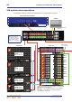
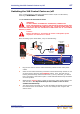
>> To connect the XL8 to the RAPIDE
Connect one of the eight ETHERNET (EtherCon® XLR) sockets on the rear of the
RAPIDE unit to the Ethernet control 1 socket of the active network (X or Y) on the
rear of the XL8 Control Centre (see “XL8 system interconnections” on page 64).
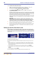
>> To daisy chain the DSP units
Important Note:
Do not connect a cable to like numbered sockets, that is, “0” to “0” or “1” to
“1”, as the DSPs will not work; socket numbers are printed to the right of each
socket.
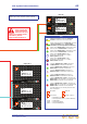
There are two default configurations available, depending on the lengths of the
interconnecting DSP cables supplied, that is, 0.25 m cables or 0.5 m cables. Both
options contain a long cable for connecting the top and bottom units, and the 0.25 m
option has an additional long cable for connecting units AMU 2 and AMU 9.
A cable’s length (cm) can be determined from a three-digit number contained
within its part number (printed on a label attached to the cable). For example, in
a part number of “14150-EZBB-050-0LC 060425TD” the “-050-” indicates a
length of 50 cm.
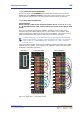
Connect the DSPs together as shown in the following diagram, according to the cables
supplied with your system. (In the diagram, the cables are coloured and the sockets
numbered to help distinguish them.)
Figure 16: Stage rack 2 - DSP wiring options
Stage rack 2
0.25 m cable option
AMU 2
AMU 3
AMU 4
AMU 5
AMU 6
AMU 7
AMU 8
AMU 9
AMU 10
AMU 1
1
1
2
6
3
8
4
7
2
9
5
8
4
10
6
9
5
3
10
7
0.5 m cable option
AMU 2
AMU 3
AMU 4
AMU 5
AMU 6
AMU 7
AMU 8
AMU 9
AMU 10
AMU 1
1
1
2
2
3
3
4
4
5
5
6
6
7
7
8
8
9
9
10
10