
User's Manual


62 Chapter 9: Setting Up The System
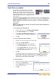
XL8 Control Centre
Quick Reference Guide
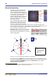
Wiring instructions
This section gives the system cabling details for the XL8-specific equipment and,
although it is laid out in recommended order, this order is not critical.
When making the connections, please make sure they match those in “XL8 system
interconnections” on page 64.
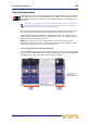
>> To connect both routers together
Important:
Without this connection system snake redundancy will be compromised.
Connect the routers via their Ethernet socket of the control expansion section on
each router’s rear panel (see “System interconnection panel” on page 253).
>> To connect the XL8 to the routers
Connect the ‘snake’ (optical or copper) from the X snake socket on the rear of the XL8
Control Centre to the appropriate snake socket on the X Router. Repeat for the Y
Router using the Y socket on the XL8 Control Centre.
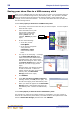
>> To connect the routers to the DSPs (Stage rack 2)
•In AES50 audio - bank 0 on the X router, connect the 10 sockets to the AES50
audio X socket on the DSP units. Repeat for the Y router, using the equivalent Y
sockets.
•In Ethernet control bank on the X router, connect the 10 sockets to the Ethernet
control X socket on the DSP units. Repeat for the Y router, using the equivalent Y
sockets.
>> To connect the routers to the Stage rack 1 units
• Mic splitters: In AES50 audio - bank 1 on the X router, connect sockets 1 and 2 to
the AES50 audio - A X sockets on the Mic Splitters. Repeat for Y router, using the
mic splitters’ Y sockets.
• Line I/O units: In AES50 audio - bank 1 on the X router, connect sockets 5 and 6
to the AES50 audio X sockets on the line I/O units. Repeat for Y router, using the
line I/O units’ equivalent Y sockets.
>> To connect the routers to the Stage rack 3 units
• Mic splitters: In AES50 audio - bank 1 on the X router, connect sockets 3 and 4
to the AES50 audio - A X sockets on the mic splitters. Repeat for the Y router,
using the mic splitters’ Y sockets.
• Line I/O unit: In AES50 audio - bank 1 on the X router, connect socket 6 to the
AES50 audio X socket on the line I/O unit. Repeat for the Y router, using the
line I/O units’ equivalent Y socket.
>> To connect the XL8 to the line I/O units (FOH rack)
Connect the AES50 audio X sockets on the rear of the XL8 Control Centre to the
AES50 audio X socket on both of the line I/O units in the FOH rack. Repeat for the Y
sockets.