
User's Manual


Front and rear connections 9
XL8 Control Centre
Quick Reference Guide
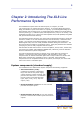
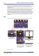
The GUI, which forms a backdrop to the control surface, represents pictorially the
layout of the control surface so that its displays are easy to follow at a glance. Not only
does it reflect what is happening on the control surface, but it also provides extra
functionality via a GUI menu. This menu lets you access all the screens that you will
require to set up, configure, manage and operate the entire XL8 Control Centre — all
from a single drop-down list of easy to follow options.
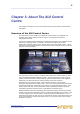
Generally, the GUIs on the input and mix bays have a channel strip on the right. This is
the equivalent of the channel strip on the control surface of each of those bays. It
displays the selected detail area of the currently selected channel.
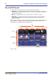
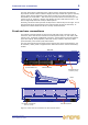
Front and rear connections
The XL8 has connector panels on the front and rear that house numerous types of
connector, which cater for the connection of mains power leads, 19” rack units, USB
memory keys, keyboards, headphones, talk mics, communications, external monitors
(input and output), KVM (keyboard, video and mouse) switches, intercoms, AES3
synchronisation, word clocks (75R) and monitors.
The rear panel also houses the mains power inlet and five mains on/off switches, one
for each bay. Mains power is supplied to the XL8 Control Centre via two PowerCon®
sockets.
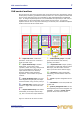
Figure 4: Front and rear connectors on XL8 Control Centre
Front view
Rear
Front
Side view
Rear view
Pull-out keyboard
Keyboard, headphones
and mic (2-off)
Internal/external
monitor (5-off)
Power supplySystem
interconnections
KVM, monitor,
synchronisation etc.