User Manual DIGITAL RACK MIXER M32R Digital Console for Live and Studio with 40 Input Channels, 16 Midas PRO Microphone Preamplifiers and 25 Mix Buses
DIGITAL RACK MIXER M32R User Manual Table of Contents Precautions.................................................................... 10 Introduction.................................................................. 11 1. Control Surface......................................................... 12 1.1 Channel Strip - Input Channels..................................... 12 1.2 Channel Strip - Group/Bus Channels.......................... 13 1.3 Config/Preamp..................................................
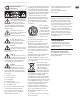
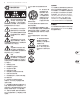
DIGITAL RACK MIXER M32R User Manual Important Safety Instructions Terminals marked with this symbol carry electrical current of sufficient magnitude to constitute risk of electric shock. Use only high-quality professional speaker cables with ¼" TS or twist-locking plugs pre-installed. All other installation or modification should be performed only by qualified personnel.
DIGITAL RACK MIXER M32R User Manual Instrucciones de seguridad Las terminales marcadas con este símbolo transportan corriente eléctrica de magnitud suficiente como para constituir un riesgo de descarga eléctrica. Utilice solo cables de altavoz profesionales y de alta calidad con conectores TS de 6,3 mm o de bayoneta prefijados. Cualquier otra instalación o modificación debe ser realizada únicamente por un técnico cualificado.
DIGITAL RACK MIXER M32R User Manual Consignes de sécurité Les points repérés par ce symbole portent une tension électrique suffisante pour constituer un risque d’électrocution. Utilisez uniquement des câbles d’enceintes professionnels de haute qualité avec fiches Jack mono 6,35 mm ou fiches à verrouillages déjà installées. Toute autre installation ou modification doit être effectuée uniquement par un personnel qualifié.
DIGITAL RACK MIXER M32R User Manual Wichtige Sicherheitshinweise Vorsicht Die mit dem Symbol markierten Anschlüsse führen so viel Spannung, dass die Gefahr eines Stromschlags besteht. Verwenden Sie nur hochwertige, professionelle Lautsprecherkabel mit vorinstallierten 6,35 mm MONO-Klinkensteckern oder Lautsprecherstecker mit Drehverriegelung. Alle anderen Installationen oder Modifikationen sollten nur von qualifiziertem Fachpersonal ausgeführt werden.
DIGITAL RACK MIXER M32R User Manual Instruções de Segurança Importantes Aviso! Terminais marcados com o símbolo carregam corrente elétrica de magnitude suficiente para constituir um risco de choque elétrico. Use apenas cabos de alto-falantes de alta qualidade com plugues TS de ¼" ou plugues com trava de torção pré-instalados. Todas as outras instalações e modificações devem ser efetuadas por pessoas qualificadas.
DIGITAL RACK MIXER M32R User Manual 安全にお使いいただくために 注意 感電の.恐れがありますので、カ バーやその他の部品を取り外 したり、開けたりしないでください。高品 質なプロ用スピーカーケーブル(¼" TS 標準 ケーブルおよびツイスト ロッキング プラ グケーブル)を使用してください。 注意 火事および感電の危険を防ぐ ため、本装置を水分や湿気の あるところには設置しないで下さい。装置 には決して水分がかからないように注意 し、花瓶など水分を含んだものは、装置の 上には置かないようにしてください。 注意 このマークが表示されている 箇所には、内部に高圧電流が 生じています。手を触れると感電の恐れが あります。 注意 取り扱いとお手入れの方法に ついての重要な説明が付属の 取扱説明書に記載されています。ご使用の 前に良くお読みください。 注意 1. 取扱説明書を通してご覧ください。 2. 取扱説明書を大切に保管してくだ さい。 3. 警告に従ってください。 4. 指示に従ってください。 5. 本機を水の近くで使用しないでくだ さい。 6.
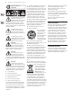
DIGITAL RACK MIXER M32R User Manual 其他的重要信息 11. 请只使用厂家指定的附属设备和 法律声明 配件。 对于任何因在此说明书提到的全部或部份 描述、 图片或声明而造成的损失, Music Tribe 不负任何责任。 技术参数和外观若有更改, 恕不另行通知。 所有的商标均为其各自所 有者的财产。 Midas, Klark Teknik, Lab Gruppen, 12. 请只使用厂家 带有此标志的终端设备具有强 大的电流, 存在触电危险。 仅限 使用带有 ¼'' TS 或扭锁式插头 的高品质专业扬声器线。 所有的安装或调 整均须由合格的专业人员进行。 指定的或随货销 售的手推车, 架子, 三角架, 支架和桌 子。 若使用手推车 来搬运设备, 请注 意安全放置设备, 以避免手推车和设 备倾倒而受伤。 13. 遇闪电雷鸣或长期不使用本设备时, 请 拔出电源插头。 14.
DIGITAL RACK MIXER M32R User Manual Precautions Before installing, setting up or operating this equipment make sure you have read and fully understand all of this section and the ‘IMPORTANT SAFETY INSTRUCTIONS’ at the front of this manual. This equipment is supplied by a mains voltage that can cause electric shock injury! The following must be observed in order to maintain safety and electromagnetic compatibility (EMC) performance. Safety warnings Signal 0V is connected internally to the chassis.
DIGITAL RACK MIXER M32R User Manual Audio connections To ensure the correct and reliable operation of your equipment, only high quality, balanced, screened, twisted pair audio cable should be used. XLR connector shells should be of metal construction so that they provide a screen when connected to the control centre and, where appropriate, they should have Pin 1 connected to the cable screen.
DIGITAL RACK MIXER M32R User Manual 1. Control Surface 1.1 Channel Strip - Input Channels (1) (2) (3) (4) (5) (6) (1) SEL Button Press to select an input or bus (depending on which layer is active) and allow it to be edited by the Channel Strip and Main Display. (2) Channel Meter This displays the signal level of the input or bus, depending on which layer is active. The COMP and GATE LEDs light to indicate that compression and/or noise gate are active.
DIGITAL RACK MIXER M32R User Manual 1.2 Channel Strip - Group/Bus Channels (1) (6) (2) (7) (3) (4) (5) (8) (9) (1) SEL Button Press to select a DCA or bus (depending on which layer is active) and allow it to be edited by the Channel Strip and Main Display. (2) Channel Meter This displays the signal level of the DCA or bus, depending on which layer is active. The PRE LED lights to indicate that the bus is sourced pre-fader, while the COMP LED lights to indicate that compression is active.
DIGITAL RACK MIXER M32R User Manual 1.3 Config/Preamp (1) (4) (2) (5) 1.4 Gate (3) (6) (1) (2) (7) (1) GAIN Rotary Control On a microphone preamplifier, input gain varies the amount of amplification applied to the microphone. Adjust the preamp gain for the selected channel with the GAIN rotary control. (2) LED Display The LED display in the Config/Preamp section illustrates the signal input level for the selected channel. This is shown as a value between 0 dB and -30 dB.
DIGITAL RACK MIXER M32R User Manual (2) LED Display The LED display illustrates when the Dynamics are functioning for the selected channel by illuminating the red COMP LED. The level of attenuation that is being applied to the signal is shown as a value between 0 dB and -30 dB. Please note that, when pressing the VIEW button, the attenuation level displayed on the Main Display shows a value of between 0 dB and -60 dB. (3) COMP Pressing the COMP button engages the compressor for the selected channel.
DIGITAL RACK MIXER M32R User Manual 1.7 Main Bus (1) (3) 1.8.1 Operation The M32R offers functionality for playing back uncompressed stereo WAV files, and for recording any stereo signal in the console directly onto USB stick or compatible USB hard drive. Note - multi-channel recording is only available via the DN32-USB card. To record to a USB stick, perform the following steps: 1. Plug a FAT-formatted (FAT12, FAT16, FAT32) USB stick into the USB port as illustrated above. 2.
DIGITAL RACK MIXER M32R User Manual 1.9 Main Display (Summary) (1) (2) (3) (3) (4) (1) DISPLAY SCREEN The controls in this section are used in conjunction with the colour screen in order to navigate and control the graphical elements it contains. By including dedicated push encoders that correspond to the adjacent controls on the screen, as well as including cursor buttons, the user can quickly navigate and control all of the colour screen’s elements.
DIGITAL RACK MIXER M32R User Manual LIBRARY The LIBRARY screen allows loading and saving of commonly-used setups for the channel inputs, effects processors, and routing scenarios. The LIBRARY screen contains the following tabs: channel: This tab allows the user to load and save commonly used combinations of the channel processing, including dynamics and EQ. effects: This tab allows the user to load and save commonly used effects processor presets.
DIGITAL RACK MIXER M32R User Manual 1.10 Monitor (1) (2) • (3) (4) (1) MONITOR LEVEL Rotary Control Adjust the level of the monitor outputs with the MONITOR LEVEL rotary control. This will be the output device connected to the sockets in the MONITOR / CONTROL ROOM OUT section on the rear panel. (2) PHONES LEVEL Rotary Control Adjust the level of the signal through the headphones or other output devices connected via the headphone jack sockets located under the front of the console.
DIGITAL RACK MIXER M32R User Manual 1.11 Talkback (1) (1) (3) (1) & (2) - TALK A / B Select the destination of the Talkback mic signal with either the TALK A or TALK B buttons. Press the VIEW button in the MONITOR section to edit the Talkback routing for A and B. (3) TALK LEVEL Rotary Control Adjust the level of the Talkback volume with the TALK LEVEL rotary control. 1.11.
DIGITAL RACK MIXER M32R User Manual 1.12 Assign SET A, B & C The set A, B & C tabs allow mapping of specific console parameters to the eight assignable buttons and four assignable rotary controls. Using these screens the user can map the exact parameters that are most useful to them to the desired controls, in the desired order. To adjust the various settings on the set A, B & C tabs, perform the following steps: 1.12.
DIGITAL RACK MIXER M32R User Manual 1.13 Fader Layer (6) (7) (1) (8) (2) (3) (6) (9) (7) (4) (5) (1) INPUTS 1-8 / 9-16 / 17-24 / 35-32 Pressing one of these buttons selects either the channel 1-8 layer, the channel 9-16 layer, the channel 17-24 layer, or the channel 25-32 layer on the left-most eight fader strips. (2) AUX IN / USB Press to select the Aux In / USB Recorder layer on the left-most eight fader strips.
DIGITAL RACK MIXER M32R User Manual 2. Main Display 2.1 Main Display - Top Section The top section of the Main Display permanently covers useful status information. The top left corner shows the selected channel number, its user-assigned name and the selected icon. The next block shows the current scene number and name in amber, as well as the next upcoming scene. The centre section displays the playback file name along with elapsed and remaining time, and a recorder status icon.
DIGITAL RACK MIXER M32R User Manual config The configuration tab allows selection of signal source/destination for the channel, configuration of insert point, and other settings, as well as configuration of the channel delay. The config tab of input channels 1-32 contains the following parameters that can be adjusted using the six push encoders: 1. Turn the first push encoder to adjust the input gain (trim) of the channel. 2.
DIGITAL RACK MIXER M32R User Manual dyn The dynamics tab displays all aspects of the channel compressor, and allows for very deep control of the effect. Whereas the top panel’s dedicated compressor section allows control of the threshold and in/out status, the dyn tab offers many more controls. This tab can be accessed directly by pressing the VIEW button in the top panel DYNAMICS section. The dyn tab contains the following parameters that can be adjusted using the six push encoders: Page 1 1.
DIGITAL RACK MIXER M32R User Manual eq The eq tab displays all aspects of the channel EQ, and also displays a detailed visual graphic of the current EQ curve. This tab can also be accessed directly by pressing the VIEW button on the top panel EQUALISER section. 1. If the currently selected channels is an input, the channel EQ contains four bands, with various aspects of each band adjusted by push encoders 2-5. 2.
DIGITAL RACK MIXER M32R User Manual main The main tab displays and controls all aspects of the main bus assignments. mix bus • Level meters, fader levels and gain reduction meters for the 16 bus masters • Level meters, fader levels and gain reduction meters for the six matrix outputs • Level meters, fader levels and gain reduction meters for the stereo main bus and the mono bus.
DIGITAL RACK MIXER M32R User Manual Pre / Post The analysers can tap their input signals from pre- or post-EQ, allowing you to see the impact of your EQ in that channel. Tap the fifth push encoder to toggles between the two. Gain When engaged, the Auto Gain function simplifies adjusting the analyser views and ensuring meaningful readings. In most cases it should be switched on.
DIGITAL RACK MIXER M32R User Manual 4. To assign an 8-channel source from the other input channels of the console (9-16, 17-24, 25-32), simply repeat the process above, using the other four push encoders on the same screen. 5. Choices for Aux 1-4 include: • Aux Ins • Local 1-2 • Local 1-4 • Local 1-6 • AES50A 1-2 • AES50A 1-4 • AES50A 1-6 • AES50B 1-2 • AES50B 1-4 • AES50B 1-6 • Card 1-2 • Card 1-4 • Card 1-6.
DIGITAL RACK MIXER M32R User Manual 3. Adjust the fourth encoder to select a specific signal path to feed the selected physical output. Choices include: • Insert Point • Main L • Main R • Main C/M • Any of the 16 Mix Outputs • Any of the six Matrix Outputs • Any of the 32 Direct Outputs • Any of the eight Auxiliary Outputs • Any of the FX Direct Outputs • Monitor L • Monitor R • Talkback. 4. Tap the fourth encoder to assign the selected output path, completing the process. 5.
DIGITAL RACK MIXER M32R User Manual To assign an output path to the option card, perform the following steps: 1. Adjust the first push encoder to select an 8-channel signal path that will be sent to the first eight channels of the card.
DIGITAL RACK MIXER M32R User Manual 2.4 Library The LIBRARY screen allows loading and saving of commonly used setups for the channel inputs, effects processors and routing scenarios. The LIBRARY screen contains the following separate tabs: channel: This tab allows the user to load and save commonly used combinations of the channel DSP effects. effects: This tab allows the user to load and save commonly used effects processor presets.
DIGITAL RACK MIXER M32R User Manual home The EFFECTS screen’s home tab provides a high-level overview of the eight effects processor slots, giving the user at-a-glance feedback on the effects they have assigned to the slots, the console source and destination for each processor, and the input/output levels for each processor. To make adjustments on the EFFECTS screen’s home tab, perform the following steps: 1.
• • DIGITAL RACK MIXER M32R User Manual Back on the EFFECTS page, press the PAGE SELECT right button to switch the screen to the editor for the Ambience processor. The screen will switch to an editor page for the first processor. Adjust the rotary encoders to tailor the effect to your liking. To apply the effect to assorted input channels, select an input channel, then adjust its “Bus Send 13” knob to taste.
DIGITAL RACK MIXER M32R User Manual 6. Adjust the 6th encoder to adjust various MIDI-based operations for the console. Choices include: • MIDI In/Out: This toggles the MIDI input and outputs for the console on/off . • Card MIDI: Allows MIDI transmission through the DN32-USB card. • USB In/Out: This toggles the console’s USB ports on/off . • RTP (Real-time Transport Protocol): This toggles on/off the console’s ability to interface with an Ethernet-based MIDI system.
DIGITAL RACK MIXER M32R User Manual preamps 2.7 Monitor Pressing the MONITOR button has the same effect as presing the VIEW button in the MONITOR panel, and is covered in detail in the MONITOR section above. 2.8 Scenes The Preamps tab allows the digital trim to be adjusted for all local and AES50 channels. 1. Adjust the 1st encoder to select a block of 8 channels. 2. Adjust encoders 2-5 to set the preamp gain for the top or bottom row of inputs. 3.
DIGITAL RACK MIXER M32R User Manual HOME The SHOW CONTROL screen’s home tab shows a general overview of the Cues that have been configured in the console, along with their custom names and what parameters are included in each Cue. A Cue is simply a single event (such as a Scene, Snippet or MIDI command) or a collection of events. These can be grouped together and stored for future recall. Up to 500 Cue entries can be stored in the M32 at any time.
DIGITAL RACK MIXER M32R User Manual Utility Pressing the UTILITY button to the right of the Main Display changes the bottom of the snippets tab to the following configuration: Each of the functions on this layer can be controlled with the adjacent push encoder as follows: Copy - Allows the user to make a copy of the currently-selected Snippet. Paste - Pastes a Snippet from the virtual clipboard. Edit - Allows the user to edit the currently-selected Snippet.
DIGITAL RACK MIXER M32R User Manual To adjust the various settings on the MIDI tab, perform the following steps: 1. Turn the first push encoder to select a Cue to edit. 2. Turn the third push encoder to select what type of MIDI event is transmitted by the console when a scene change is issued. The choices include: • Off (no MIDI event) • MIDI Program Change • MIDI Control Change • Note. 3. Push encoders 4, 5 and 6 adjust the channel, number and value or velocity, where applicable.
DIGITAL RACK MIXER M32R User Manual 2.11 Internal Effects Rich Plate Reverb The M32R contains over 60 internal effects that can be applied to each of the input channels, either as inserts or as sends and returns. Access the internal effects by pressing the EFFECTS button next to the Main Display. The functionality for each of the effects is detailed below. Note - for information on routing channels to the FX processors, see Chapter 2.5 Effects.
DIGITAL RACK MIXER M32R User Manual Chamber Reverb Vintage Reverb Chamber Reverb simulates the reverberation found in medium sized spaces, somewhere between the intimacy of a small room, and the grandeur of a large hall. Inspired by the Lexicon Chamber Reverb. The PRE DELAY slider controls the amount of time before the reverberation is heard following the source signal. DECAY controls the amount of time it takes for the reverb to dissipate.
DIGITAL RACK MIXER M32R User Manual Gated Reverb This effect was originally achieved by combining a reverb with a noise gate. Our gated reverb creates the same impression by a special shaping of the reverb tail. Gated Reverb is especially effective for creating a 1980’s-style snare sound, or to enlarge the presence of a kick drum. Inspired by the Lexicon 300/480L. PRE DELAY controls the amount of time before the reverberation is heard following the source signal.
DIGITAL RACK MIXER M32R User Manual Stereo Chorus Chorus samples the input, slightly detunes it and mixes it with the original signal to produce a somewhat thicker, shimmering sound. Use it to thicken up background vocals, or to double the sound of brass and woodwind instruments. Whereas DELAY L / R set the total amount of delay for the left and right channels, WIDTH L / R determines the amount of modulated delay taken from either the left or right channels.
DIGITAL RACK MIXER M32R User Manual Rotary Speaker Delay + Chamber Rotary Speaker emulates the sound of a Leslie rotating speaker. The M32’s Rotary Speaker provides more flexibility than its electro-mechanical counterpart, and can be used with a variety of instruments, and even vocals, to create a whirling, psychedelic effect. The LO SPEED and HI SPEED push encoders adjust the rotation speed of the Slow and Fast speed selection, and can be toggled with the FAST button.
DIGITAL RACK MIXER M32R User Manual langer + Chamber Delay + Flanger Add the mind-bending, filter-sweeping effect of a state-of-the-art flanger to the elegant sweetening of a traditional chamber reverb - all in one FX slot. Inspired by the Lexicon PCM 70. The BALANCE push encoder adjusts the balance between flanger and reverb. Low frequencies can be excluded with the LO CUT push encoder, and the MIX push encoder adjusts how much of the effect is added to the signal.
DIGITAL RACK MIXER M32R User Manual Dual Graphic EQ / Stereo Graphic EQ / Dual TruEQ / Stereo TruEQ Graphic EQ with frequency response correction. Dual DeEsser / Stereo DeEsser There are four standard graphic EQs that provide 31 bands of adjustment between 20 Hz and 20 kHz. A master volume slider compensates for changes in volume caused by the EQ. A maximum boost or cut of 15 dB is available for each band.
DIGITAL RACK MIXER M32R User Manual Stereo Xtec EQ5 / Dual Xtec EQ5 level of the processed signal. SQUEEZE adds compression to the signal to add punch and a slight distortion depending on the amount you dial in. ATTACK sets the attack time, ranging from 0.05 ms to 1 ms. RELEASE adjusts the release time from 0.05 ms to 1.04 seconds. KNEE adjusts the soft limiting threshold point from hard limiting (0 dB) to maximum soft limiting (10 dB).
DIGITAL RACK MIXER M32R User Manual Fair Comp / M/S Fair Comp / Dual Fair Comp This classic tube compressor not only achieves record bids in high-end vintage gear auctions, it also delivers some of the finest colourations in compressor history. Two small trim VRs preset the control side chain action, a six-step switch determines the timing, and the two large Input and Threshold knobs adjust the levels.
DIGITAL RACK MIXER M32R User Manual Dual Exciter / Stereo Exciter Exciters increase presence and intelligibility in live sound applications, and are indispensable for adding clarity, air and harmonic overtones in the recording studio. This effect is particularly useful for filling out the sound in difficult rooms, and for producing a more natural live or recorded sound. Inspired by the famous Aphex Aural Exciter.
DIGITAL RACK MIXER M32R User Manual Dual Tube Stage / Stereo Tube Stage 3. Rear Panel 3.1 MONITOR / CONTROL ROOM OUT (1) (2) (1) Talkback Microphone Input Connect a talkback mic via standard XLR cable. (2) BAL / UNBAL Left & Right Jack Sockets Connect a pair of studio monitors using standard ¼" cables. Tube Stage / Overdrive is a versatile effect capable of emulating a variety of modern and classic tube amps.
DIGITAL RACK MIXER M32R User Manual 3.5 Klark Teknik DN32-USB 3.9 AES50 DN32 USB Transmit up to 32 channels of audio to and from a computer using the DN32 USB audio interface. Transmit up to 96 channels in and out via Ethernet cables. 3.6 REMOTE CONTROL Connect to and from external equipment via ¼” or RCA cables. 3.10 AUX IN / OUT (1) ETHERNET Connect to a PC for remote control operation via Ethernet. See chapter 2.6 Setup - Network for wireless connection details. 3.
DIGITAL RACK MIXER M32R User Manual 4. Appendices Mic Input Characteristics 4.1 Appendix A: Technical Specifications Processing Input Processing Channels Output Processing Channels 16 aux buses, 6 matrices, main LRC Internal Effects Engines (True Stereo / Mono) Internal Show Automation (structured Cues / Snippets) Internal Total Recall Scenes (incl.
DIGITAL RACK MIXER M32R User Manual 4.2 Appendix B: MIDI Operation Display Main Screen Channel LCD Screen Main Meter 5" TFT LCD, 800 x 480 Resolution, 262k Colours 128 x 64 LCD with RGB Colour Backlight 18 Segment (-45 dB to Clip) Power Switch-Mode Power Supply Power Consumption Auto-Ranging 100-240 VAC (50/60 Hz) ± 10% 70 W Physical Standard Operating Temperature Range Dimensions Weight * A-weighted figures are typically ~3 dB better 5°C – 40°C (41°F – 104°F) 478 x 617 x 208 mm (18.8 x 24.
DIGITAL RACK MIXER M32R User Manual Permanent MIDI Assignments Overview (Remote Off) MIDI RX MIDI Ch Controller Value Comment Scenes Snippet Cue Mute Groups 1 2 3-6 2 Program Change Program Change Program Change CC80-85 1-100 1-100 0-127 on (127) / off (0), toggle latching Faders 1 CC0-79 0-127 Mute 2 CC0-79 on (127) / off (0), toggle latching Pan 2 CC0-79 0-127 MIDI TX Mute Groups Faders Mute Pan MIDI Ch 2 1 2 3 Controller CC80-85 CC80-79 CC80-79 CC80-79 Value 95 = 0dB Value
DIGITAL RACK MIXER M32R User Manual MIDI CC (raw) selected and Remote is enabled+active, the group section controls will transmit/receive the following messages: MIDI RX MIDI Ch Controller Comment Group 1-8 SELECT Group 1-8 SOLO Group 1-8 MUTE Sends On Fader 1 1 1 1 Note 64-71 CC 32-39 CC 40-47 CC 48 on (127) / off (0), push non-latching on (127) / off (0), toggle latching on (127) / off (0), toggle latching on (127) / off (0), toggle latching Group DCA 1-8 1 Note 72 on (127) / off (0), push
DIGITAL RACK MIXER M32R User Manual 4.
DIGITAL RACK MIXER M32R User Manual Rear View Side View
A/D AUX RETURN (1-6) SLOT (32ch OUT) AES-50 B (48ch OUT) AES-50 A (48ch OUT) SLOT (32ch IN) AES-50 B (48ch IN) AES-50 A (48ch IN) A/D PHANTOM MONITOR L+C/R+C OUT MONITOR SOURCE IN MONITOR LR OUT MAIN LRC PRE EQ OUT MAIN LRC OUT MATRIX 1-6 OUT MIX 1-16 OUT PATCH CUE MAIN LRC INSERT SEND MAIN LRC INSERT RETURN MATRIX 1-6 INSERT SEND MATRIX 1-6 INSERT RETURN MIX 1-16 INSERT SEND MIX 1-16 INSERT RETURN FX 1-8 IN (L / R) INPUT (1-32) +48V USB PLAY USB REC FX 1-8 OUT (L / R) Revision
DIGITAL RACK MIXER M32R User Manual 4.5 Appendix E: Service Information This appendix contains routine service information for the M32R Digital Console. Routine Maintenance To help keep your M32R Digital Console unit in good working order and to make sure it gives you optimum performance, we recommend that you carry out the following about once every month. • Clean the control centre, as detailed in ‘Cleaning the control centre’ (below) • Check controls for freedom of operation.
DIGITAL RACK MIXER M32R User Manual Bank: A fixed number of channels displayed on a GUI screen. Bass: Lower frequencies in a signal. Bay: One of the main control surface sections. Bus: A pathway down which one or more signals can travel. C Cat 5e: A specification for a type of cable used typically for Ethernet computer networks. Channel: Single path taken by an audio signal (input or output) through the control centre.
DIGITAL RACK MIXER M32R User Manual GUI menu: A menu selectable at either GUI screen by clicking the home button (upper-left corner). GUI screen: One of the M32’s two screens, which comprise the GUI. H HPF: Abbreviation for ‘high pass filter’. A filter that removes lower frequencies from a signal, leaving the higher frequencies unaffected. Hum: Undesirable low frequency tone present in a signal due to grounding problems or proximity to a power source. Hz: Symbol for ‘Hertz’.
DIGITAL RACK MIXER M32R User Manual Output fast strip: One of 16 channel strips in the output fast zone. Provides detailed control of the currently selected outputs. See Output fast zone. Output fast zone: Control area for fast access to primary main output functions. Overload: A condition where the signal level is too high. Overview: The main view in the GUI channel strip, which contains the control sections of the selected channel. This represents the associated channel strip on the control surface.
DIGITAL RACK MIXER M32R User Manual Surround: Audio that has more that two speaker locations and, therefore, more than two channels. Also commonly termed ‘surround sound’. Synchronisation (sync): Coordination of timing between devices. T Tab: A ‘sheet’ in the From and To sections that contains a specific group of patch connectors. See Patching. TFT: Abbreviation for ‘thin film transistor’. Threshold: Level at which dynamics processing will begin to operate.
DIGITAL RACK MIXER M32R User Manual Other important information Important information 1. Register online. Please register your new Music Tribe equipment right after you purchase it by visiting behringer.com. Registering your purchase using our simple online form helps us to process your repair claims more quickly and efficiently. Also, read the terms and conditions of our warranty, if applicable. 2. Malfunction.
DIGITAL RACK MIXER M32R User Manual 其他的重要信息 1. 在线注册。 请购买 Music Tribe 产品后立即 在 midasconsoles.com 网站注册。 网页上有简单 的在线注册表格。 这有助于我们更快更有效 率地处理您维修等事宜。 请阅读保修的相关 条款及条件。 2. 无法正常工作。 若您的 Music Tribe 产品 无法正常工作, 我们会为您尽快修复。 请联 系您购买产品的销售商。 若你所在地区没有 Music Tribe 销售商, 请联系 midasconsoles.com 网站的 “ WHERE TO BUY ” 一栏下的所列出的子 公司或经销商。 3.
DIGITAL RACK MIXER M32R USER MANUAL FEDERAL COMMUNICATIONS COMMISSION COMPLIANCE INFORMATION DIGITAL RACK MIXER M32R Responsible Party Name: Music Tribe Brands UK Ltd.
DIGITAL RACK MIXER M32R User Manual