
User Manual


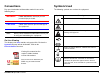
Table Of Contents
- About This Manual
- Copyright
- Proprietary Material
- Quality Certification
- Regulatory Status
- Conventions
- Symbols Used
- Warranty Information
- Introduction
- Product Description
- Routine Operation
- 3.1 Chapter Overview
- 3.2 Overview of Controls, Indicators, and Connectors
- 3.3 Preparing for Operation
- 3.4 Using the STRATA TX Screens
- 3.5 TXU and/or TCU Monitoring Operations
- 3.5.1 Using the Monitor Screens in MPEG Output Mode
- 3.5.2 Using the Monitor Screens in Ext IF Input Mode
- 3.5.3 Using the Monitor Screens in COFDM - IF Mode
- 3.5.4 Using the Monitor Screens in COFDM ASI In Mode
- 3.5.5 Using the Monitor Screens in Analog - IF Mode
- 3.5.6 Using the Monitor Screens in DVB-S Mode
- 3.6 TXU and/or TCU Control Operations
- 3.7 Front Panel vs. STRATA TX Configurator Settings
- Table 3-1: Front Panel vs. Configurator Settings
- Troubleshooting
- Channels & Frequencies
- A.1 Appendix Overview
- A.2 Initial Factory Presets
- A.2.1 3.4 to 3.8 GHz Channel Plan
- A.2.2 4.4 to 5.0 GHz Channel Plan
- A.2.3 6.4 to 7.1 GHz Channel Plan
- A.2.4 6.9 to 7.5 GHz Channel Plan
- A.2.5 7.4 to 8.0 GHz Channel Plan
- A.2.6 7.8 to 8.5 GHz Channel Plan
- A.2.7 8.2 to 8.9 GHz Channel Plan
- A.2.8 10.0 to 10.7 GHz Channel Plan
- A.2.9 10.5 to 11.2 GHz Channel Plan
- A.2.10 10.8 to 11.5 GHz Channel Plan
- A.2.11 12.7 to 13.25 GHz Channel Plan
- Glossary
- Specifications

iiSTRATA TX Operator’s Guide
Conventions
Pay special attention to information marked in one of the
following ways:
WARNING
Follow WARNINGS closely to prevent
personal injury or death.
CAUTION
Follow CAUTIONS to prevent damage to
the equipment.
Note
Notes provide additional information to assist you
in using and maintaining the equipment.
On-Line Viewing
Text displayed as blue contains a hypertext link. Click on the
hypertext to jump to that destination. Click on the
blue destination to return.
Viewing this manual on-line
requires Adobe Acrobat,
version 4.0 or above.
Click on this icon to download your
FREE copy of Adobe Acrobat
Reader.
Symbols Used
The following symbols are used on the equipment:
Symbol Meaning
WARNING: General Warning. Risk of Danger
WARNING: Risk of Electric Shock
WARNING: Electrostatic Discharge. Possible
Damage to Equipment
- OR -
Fuse - Identifies fuses or their location.
Frame or Chassis Ground - Identifies the frame or
chassis terminal.
Earth Ground - Identifies the earth Ground Terminal
Protective Earth Ground - Identifies any terminal
which is intended for connection to an external
conductor for protection against electric shock in
case of a fault, or the terminal on a protective earth
electrode.