
User Manual
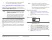

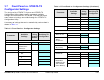


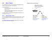

Table Of Contents
- About This Manual
- Copyright
- Proprietary Material
- Quality Certification
- Regulatory Status
- Conventions
- Symbols Used
- Warranty Information
- Introduction
- Product Description
- Routine Operation
- 3.1 Chapter Overview
- 3.2 Overview of Controls, Indicators, and Connectors
- 3.3 Preparing for Operation
- 3.4 Using the STRATA TX Screens
- 3.5 TXU and/or TCU Monitoring Operations
- 3.5.1 Using the Monitor Screens in MPEG Output Mode
- 3.5.2 Using the Monitor Screens in Ext IF Input Mode
- 3.5.3 Using the Monitor Screens in COFDM - IF Mode
- 3.5.4 Using the Monitor Screens in COFDM ASI In Mode
- 3.5.5 Using the Monitor Screens in Analog - IF Mode
- 3.5.6 Using the Monitor Screens in DVB-S Mode
- 3.6 TXU and/or TCU Control Operations
- 3.7 Front Panel vs. STRATA TX Configurator Settings
- Table 3-1: Front Panel vs. Configurator Settings
- Troubleshooting
- Channels & Frequencies
- A.1 Appendix Overview
- A.2 Initial Factory Presets
- A.2.1 3.4 to 3.8 GHz Channel Plan
- A.2.2 4.4 to 5.0 GHz Channel Plan
- A.2.3 6.4 to 7.1 GHz Channel Plan
- A.2.4 6.9 to 7.5 GHz Channel Plan
- A.2.5 7.4 to 8.0 GHz Channel Plan
- A.2.6 7.8 to 8.5 GHz Channel Plan
- A.2.7 8.2 to 8.9 GHz Channel Plan
- A.2.8 10.0 to 10.7 GHz Channel Plan
- A.2.9 10.5 to 11.2 GHz Channel Plan
- A.2.10 10.8 to 11.5 GHz Channel Plan
- A.2.11 12.7 to 13.25 GHz Channel Plan
- Glossary
- Specifications

4
Troubleshooting 4-1STRATA TX Operator’s Guide/Tech Ref Manual
Troubleshooting
4.1 Chapter Overview
This chapter describes how to troubleshoot your STRATA TX
System.
Here are the topics covered:
4.2 Status LED
Above the PWR switch on both the TXU and TCU is a multi-
color Status LED. The LED indications are listed in Table 4-1.
Topic Page
Status LED 4-1
Messages on Display 4-1
Error Codes 4-3
Operational Problems 4-8
WARNING
A Major Alarm may also indicate a potential
safety hazard. Shut down the STRATA TX
System and disconnect power.
4.3 Messages on Display
One of the ways the STRATA TX System will alert you to problems is
by error messages on the TXU and/or TCU front panel displays.
These are displayed on the Monitor Screens.
See Table 4-2 on page 4-2 for descriptions of the messages and
what to do when they appear.
Table 4-1: Status LED Indications
LED
Color
Meaning Suggested Action
----- Power is not on in that unit. Turn on power, as required.
Green Power is on and no errors
are detected.
None.
Amber Minor Alarm - Power is on
but some part of the system
reports an abnormal
condition that requires
attention. Condition might
impair performance.
Check Monitor Screens for
error messages or Error
Codes. Troubleshoot using
tables in this chapter.
Red Major Alarm - Power is on
but there is a serious failure
or error that will prevent
normal operation. The
internal processors are not
running.
Turn off unit and
disconnect power.