
User Manual
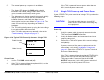
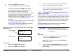
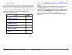
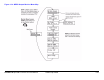
Table Of Contents
- About This Manual
- Copyright
- Proprietary Material
- Quality Certification
- Regulatory Status
- Conventions
- Symbols Used
- Warranty Information
- Introduction
- Product Description
- Routine Operation
- 3.1 Chapter Overview
- 3.2 Overview of Controls, Indicators, and Connectors
- 3.3 Preparing for Operation
- 3.4 Using the STRATA TX Screens
- 3.5 TXU and/or TCU Monitoring Operations
- 3.5.1 Using the Monitor Screens in MPEG Output Mode
- 3.5.2 Using the Monitor Screens in Ext IF Input Mode
- 3.5.3 Using the Monitor Screens in COFDM - IF Mode
- 3.5.4 Using the Monitor Screens in COFDM ASI In Mode
- 3.5.5 Using the Monitor Screens in Analog - IF Mode
- 3.5.6 Using the Monitor Screens in DVB-S Mode
- 3.6 TXU and/or TCU Control Operations
- 3.7 Front Panel vs. STRATA TX Configurator Settings
- Table 3-1: Front Panel vs. Configurator Settings
- Troubleshooting
- Channels & Frequencies
- A.1 Appendix Overview
- A.2 Initial Factory Presets
- A.2.1 3.4 to 3.8 GHz Channel Plan
- A.2.2 4.4 to 5.0 GHz Channel Plan
- A.2.3 6.4 to 7.1 GHz Channel Plan
- A.2.4 6.9 to 7.5 GHz Channel Plan
- A.2.5 7.4 to 8.0 GHz Channel Plan
- A.2.6 7.8 to 8.5 GHz Channel Plan
- A.2.7 8.2 to 8.9 GHz Channel Plan
- A.2.8 10.0 to 10.7 GHz Channel Plan
- A.2.9 10.5 to 11.2 GHz Channel Plan
- A.2.10 10.8 to 11.5 GHz Channel Plan
- A.2.11 12.7 to 13.25 GHz Channel Plan
- Glossary
- Specifications

Routine Operation 3-15STRATA TX Operator’s Guide/Tech Ref Manual
If the TXU is powered from a source other than an
ACU, turn that power source on.
4. Set the TXU PWR switch to I (on).
5. The normal power-up sequence is as follows:
- The Status LED above the PWR switch should
illuminate and should change colors from red, to
green, to amber, and finally remain green.
- The alphanumeric display should light up and quickly
display a self-test screen, then the version of the
installed firmware, and finally the Main Screen.
Some typical screens are shown in Figure 3-11. The
exact screens will vary depending on installed
hardware.
- The TXU will typically power up using the last settings
in use when power was turned off.
- If the TXU does not power up normally, refer to the
“Troubleshooting” Chapter on page 4-1.
Figure 3-11: Typical TXU Power Up Screens - Single TXU
STRATA TX
V X.X.X
Preset 1
0.00W
Radio Version
Main Screen
Power Down
1. Set the TXU PWR switch to 0 (off).
2. If the TXU is powered from the optional ACU, set the
ACU power switch to 0 (off).
If the TXU is powered from a source other than an
ACU, turn that power source off.
3.3.6 TXU and TCU Power Up and Power Down -
Co-Located
If your STRATA TX System consists of a co-located TXU and a
TCU, it is recommended that both the TCU and TXU be powered
from the same DC power supply in lieu of using superimposed
DC power on the coaxial cable between the TCU and the TXU.
Note
The following procedure reflects use of a single DC
power source for both the TXU and TCU in lieu of
using superimposed DC power on the coaxial
cable between the TCU and the TXU.
Perform the following steps to power up or power down a co-
located TX System:
CAUTION
To avoid possible damage, turn off DC
Power on the coax before connecting any
test equipment.