
User Manual


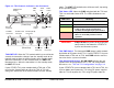


Table Of Contents
- About This Manual
- Copyright
- Proprietary Material
- Quality Certification
- Regulatory Status
- Conventions
- Symbols Used
- Warranty Information
- Introduction
- Product Description
- Routine Operation
- 3.1 Chapter Overview
- 3.2 Overview of Controls, Indicators, and Connectors
- 3.3 Preparing for Operation
- 3.4 Using the STRATA TX Screens
- 3.5 TXU and/or TCU Monitoring Operations
- 3.5.1 Using the Monitor Screens in MPEG Output Mode
- 3.5.2 Using the Monitor Screens in Ext IF Input Mode
- 3.5.3 Using the Monitor Screens in COFDM - IF Mode
- 3.5.4 Using the Monitor Screens in COFDM ASI In Mode
- 3.5.5 Using the Monitor Screens in Analog - IF Mode
- 3.5.6 Using the Monitor Screens in DVB-S Mode
- 3.6 TXU and/or TCU Control Operations
- 3.7 Front Panel vs. STRATA TX Configurator Settings
- Table 3-1: Front Panel vs. Configurator Settings
- Troubleshooting
- Channels & Frequencies
- A.1 Appendix Overview
- A.2 Initial Factory Presets
- A.2.1 3.4 to 3.8 GHz Channel Plan
- A.2.2 4.4 to 5.0 GHz Channel Plan
- A.2.3 6.4 to 7.1 GHz Channel Plan
- A.2.4 6.9 to 7.5 GHz Channel Plan
- A.2.5 7.4 to 8.0 GHz Channel Plan
- A.2.6 7.8 to 8.5 GHz Channel Plan
- A.2.7 8.2 to 8.9 GHz Channel Plan
- A.2.8 10.0 to 10.7 GHz Channel Plan
- A.2.9 10.5 to 11.2 GHz Channel Plan
- A.2.10 10.8 to 11.5 GHz Channel Plan
- A.2.11 12.7 to 13.25 GHz Channel Plan
- Glossary
- Specifications

Routine Operation 3-6STRATA TX Operator’s Guide/Tech Ref Manual
Figure 3-3: TCU Controls, Indicators, and Connectors
TCU XMIT LED When the TCU control switch is pressed for one
second, the transmitter changes from the standby mode to the
transmit mode or from the transmit mode to the standby mode.
When the transmitter is in the transmit mode, the XMIT LED
illuminates blue. When the transmitter is in the standby mode,
the XMIT LED is off.
If your STRATA TX System contains both a TXU and a TCU,
pressing the Control switch on either the TXU or TCU will
change the transmitter to the transmit mode or to the standby
TCU
TX
XMIT
(Rear View)
(Front View)
DC ON COAX
Switch
SIGNAL IN
Connector
Monitor (MON)
Connector
SIGNAL OUT
Connector
POWER
Connector
RS-232
Connector
AUDIO
Connector
Alphanumeric
Display
Control
Switch
PWR
Switch
Status
LED
XMIT
LED
mode. The XMIT LED on both units will be on or off, depending
on the operating mode.
TCU Status LED Above the PWR switch on both the TXU and
TCU is a multi-color Status LED. The LED indications are as
follows:
WARNING
A Major Alarm may also indicate a potential
safety hazard. Shut down the STRATA TX
System and disconnect power.
TCU PWR Switch The front panel PWR (power) switch controls
application of DC power to the TCU. If your STRATA TX System
contains both a TXU and an TCU, both PWR switches must be
turned on for the system to function.
TCU DC ON COAX Switch DC ON COAX switches are not
contained on all configurations of the TCU. For configuration
differences, see “TXU and TCU Configurations” on page 2-9.
If your STRATA TX System contains both a TXU and a TCU, the
System allows you to power the TXU using DC power supplied
from the TCU or to power the TCU using DC power from the
LED Color Meaning
----- Power is not on in that unit.
Green Power is on and no errors are detected.
Amber Minor Alarm - Power is on but some part
of the system reports an abnormal
condition that might impair performance.
Red Major Alarm - Power is on but there is a
failure or error that prevents normal
operation.