
User Manual


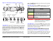


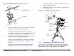
Table Of Contents
- About This Manual
- Copyright
- Proprietary Material
- Quality Certification
- Regulatory Status
- Conventions
- Symbols Used
- Warranty Information
- Introduction
- Product Description
- Routine Operation
- 3.1 Chapter Overview
- 3.2 Overview of Controls, Indicators, and Connectors
- 3.3 Preparing for Operation
- 3.4 Using the STRATA TX Screens
- 3.5 TXU and/or TCU Monitoring Operations
- 3.5.1 Using the Monitor Screens in MPEG Output Mode
- 3.5.2 Using the Monitor Screens in Ext IF Input Mode
- 3.5.3 Using the Monitor Screens in COFDM - IF Mode
- 3.5.4 Using the Monitor Screens in COFDM ASI In Mode
- 3.5.5 Using the Monitor Screens in Analog - IF Mode
- 3.5.6 Using the Monitor Screens in DVB-S Mode
- 3.6 TXU and/or TCU Control Operations
- 3.7 Front Panel vs. STRATA TX Configurator Settings
- Table 3-1: Front Panel vs. Configurator Settings
- Troubleshooting
- Channels & Frequencies
- A.1 Appendix Overview
- A.2 Initial Factory Presets
- A.2.1 3.4 to 3.8 GHz Channel Plan
- A.2.2 4.4 to 5.0 GHz Channel Plan
- A.2.3 6.4 to 7.1 GHz Channel Plan
- A.2.4 6.9 to 7.5 GHz Channel Plan
- A.2.5 7.4 to 8.0 GHz Channel Plan
- A.2.6 7.8 to 8.5 GHz Channel Plan
- A.2.7 8.2 to 8.9 GHz Channel Plan
- A.2.8 10.0 to 10.7 GHz Channel Plan
- A.2.9 10.5 to 11.2 GHz Channel Plan
- A.2.10 10.8 to 11.5 GHz Channel Plan
- A.2.11 12.7 to 13.25 GHz Channel Plan
- Glossary
- Specifications

Routine Operation 3-5STRATA TX Operator’s Guide/Tech Ref Manual
TXU RF Output Connector The RF output connector is a type
N connector that allows connection to an antenna.
TXU RS-232 Connector The RS-232 connector provides
connection to a Windows-based PC when using the STRATA TX
Configuration Utility software.
This connector also provides connection to the STRATA
Standard or Aircraft Remote Control Panel when used in mobile
or aircraft operations.
Pressing the control switch causes an
action to occur.
Command Options
• If the displayed setting is Chng Preset, Set
Channel, or Set PowerOut, pressing the
control switch causes the displayed setting to
blink.
Turning the control switch cw or ccw then
displays the other options for that setting.
When the desired option is displayed,
pressing the control switch selects that
option.
• If the displayed setting is 75 Ohm Coax,
pressing the control switch causes the setting
to switch to the other choice (i.e., if 75 Ohm
Coax Power Off is displayed, pressing the
control switch will select 75 Ohm Coax
Power On).
Transmit
• Pressing the control switch for one second
changes the transmitter to the transmit mode
from the standby mode.
• Pressing the control switch for one second
changes the transmitter from the transmit
mode to the standby mode.
3.2.2 TCU Controls, Indicators, and Connectors
Controls, indicators, and connectors contained on the TCU are
identified and described below. Topics covered are as follows:
Each of these controls, indicators, and connectors are described
in the following paragraphs. Controls, indicators, and connectors
contained on the TCU are shown in Figure 3-3 on page 3-6. For
configuration differences in the TCU, see “TXU and TCU
Configurations” on page 2-9.
The TCU is configured using Windows PC-based STRATA TX
Configuration Utility software. For details, see the “Advanced
Operation” Chapter on page 5-1 chapter (part of the STRATA TX
System Technical Reference Manual only).
TCU Alphanumeric Display The TCU contains a two-line by
12-character alphanumeric display. The display works in
conjunction with the control switch to allow you to monitor
system status and to control system settings.
Topic Page
TCU Alphanumeric Display 3-6
TCU XMIT LED 3-6
TCU Status LED 3-6
TCU PWR Switch 3-6
TCU DC ON COAX Switch 3-6
TCU Control Switch 3-7
TCU RS-232 Connector 3-8
TCU POWER Connector 3-8
TCU SIGNAL OUT Connector 3-8
TCU Monitor (MON) Connector 3-8
TCU SIGNAL IN Connector 3-8
TCU AUDIO Connector 3-8