
User Manual
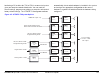
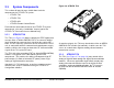
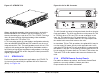
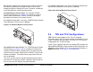
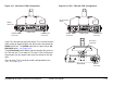
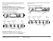
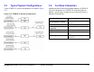
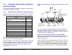
Table Of Contents
- About This Manual
- Copyright
- Proprietary Material
- Quality Certification
- Regulatory Status
- Conventions
- Symbols Used
- Warranty Information
- Introduction
- Product Description
- Routine Operation
- 3.1 Chapter Overview
- 3.2 Overview of Controls, Indicators, and Connectors
- 3.3 Preparing for Operation
- 3.4 Using the STRATA TX Screens
- 3.5 TXU and/or TCU Monitoring Operations
- 3.5.1 Using the Monitor Screens in MPEG Output Mode
- 3.5.2 Using the Monitor Screens in Ext IF Input Mode
- 3.5.3 Using the Monitor Screens in COFDM - IF Mode
- 3.5.4 Using the Monitor Screens in COFDM ASI In Mode
- 3.5.5 Using the Monitor Screens in Analog - IF Mode
- 3.5.6 Using the Monitor Screens in DVB-S Mode
- 3.6 TXU and/or TCU Control Operations
- 3.7 Front Panel vs. STRATA TX Configurator Settings
- Table 3-1: Front Panel vs. Configurator Settings
- Troubleshooting
- Channels & Frequencies
- A.1 Appendix Overview
- A.2 Initial Factory Presets
- A.2.1 3.4 to 3.8 GHz Channel Plan
- A.2.2 4.4 to 5.0 GHz Channel Plan
- A.2.3 6.4 to 7.1 GHz Channel Plan
- A.2.4 6.9 to 7.5 GHz Channel Plan
- A.2.5 7.4 to 8.0 GHz Channel Plan
- A.2.6 7.8 to 8.5 GHz Channel Plan
- A.2.7 8.2 to 8.9 GHz Channel Plan
- A.2.8 10.0 to 10.7 GHz Channel Plan
- A.2.9 10.5 to 11.2 GHz Channel Plan
- A.2.10 10.8 to 11.5 GHz Channel Plan
- A.2.11 12.7 to 13.25 GHz Channel Plan
- Glossary
- Specifications

Routine Operation 3-2STRATA TX Operator’s Guide/Tech Ref Manual
3.2 Overview of Controls, Indicators,
and Connectors
This section describes the controls, indicators, and connectors
used on the STRATA TX System.
3.2.1 TXU Controls, Indicators, and Connectors
Controls, indicators, and connectors contained on the TXU are
identified and described below. Topics covered are as follows:
Each of these controls, indicators, and connectors are described
in more detail in the following paragraphs.
Controls, indicators, and connectors contained on the TXU front
panel are shown in Figure 3-1. Connectors contained on the
TXU rear panel are shown in Figure 3-2 on page 3-3. For
configuration differences in the TXU, see “TXU and TCU
Configurations” on page 2-9.
Topic Page
TXU Front Panel DC ON COAX
Switch
3-2
TXU SIGNAL INPUT Connector 3-3
TXU AUDIO Connector 3-3
TXU Alphanumeric Display 3-3
TXU XMIT LED 3-3
TXU Status LED 3-4
TXU PWR/RS-485 Connector 3-4
TXU PWR Switch 3-4
TXU Control Switch 3-4
TXU RF Output Connector 3-5
TXU RS-232 Connector 3-5
Figure 3-1: TXU Controls, Indicators, and Connectors - Front
View
The TXU is configured using Windows PC-based STRATA TX
Configuration Utility software. For details, see the “Advanced
Operation” Chapter on page 5-1 (part of the STRATA TX System
Technical Reference Manual only).
TXU Front Panel DC ON COAX Switch DC ON COAX
switches are not contained on all configurations of the TXU. For
configuration differences, see “TXU and TCU Configurations”
Chapter on page 2-9.
If your STRATA TX System contains both a TXU and a TCU, the
System allows you to power the TXU using DC power supplied
from the TCU or allows you to power the TCU using DC power
from the TXU. This DC power is superimposed on the coaxial
cable between the TCU and the TXU. This DC power option is
DO NOT
EXCEED
36 VOLTS DC
DC
ON COAX
OFF ON
SIGNAL
INPUT
Connector
Alpha-
numeric
Display
Status
LED
DC ON COAX
Switch or AUDIO
Connector
Control
Switch
Power
Switch
PWR/RS-485
Connector
XMIT
LED