
User Manual
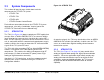
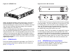
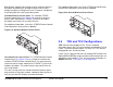
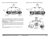
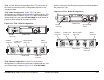
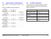
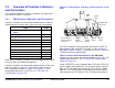
Table Of Contents
- About This Manual
- Copyright
- Proprietary Material
- Quality Certification
- Regulatory Status
- Conventions
- Symbols Used
- Warranty Information
- Introduction
- Product Description
- Routine Operation
- 3.1 Chapter Overview
- 3.2 Overview of Controls, Indicators, and Connectors
- 3.3 Preparing for Operation
- 3.4 Using the STRATA TX Screens
- 3.5 TXU and/or TCU Monitoring Operations
- 3.5.1 Using the Monitor Screens in MPEG Output Mode
- 3.5.2 Using the Monitor Screens in Ext IF Input Mode
- 3.5.3 Using the Monitor Screens in COFDM - IF Mode
- 3.5.4 Using the Monitor Screens in COFDM ASI In Mode
- 3.5.5 Using the Monitor Screens in Analog - IF Mode
- 3.5.6 Using the Monitor Screens in DVB-S Mode
- 3.6 TXU and/or TCU Control Operations
- 3.7 Front Panel vs. STRATA TX Configurator Settings
- Table 3-1: Front Panel vs. Configurator Settings
- Troubleshooting
- Channels & Frequencies
- A.1 Appendix Overview
- A.2 Initial Factory Presets
- A.2.1 3.4 to 3.8 GHz Channel Plan
- A.2.2 4.4 to 5.0 GHz Channel Plan
- A.2.3 6.4 to 7.1 GHz Channel Plan
- A.2.4 6.9 to 7.5 GHz Channel Plan
- A.2.5 7.4 to 8.0 GHz Channel Plan
- A.2.6 7.8 to 8.5 GHz Channel Plan
- A.2.7 8.2 to 8.9 GHz Channel Plan
- A.2.8 10.0 to 10.7 GHz Channel Plan
- A.2.9 10.5 to 11.2 GHz Channel Plan
- A.2.10 10.8 to 11.5 GHz Channel Plan
- A.2.11 12.7 to 13.25 GHz Channel Plan
- Glossary
- Specifications

Product Description 2-10STRATA TX Operator’s Guide/Tech Ref Manual
Figure 2-11: Standalone TXU Configuration
If your TXU was ordered to operate with a TCU, it will not contain
either analog or digital modules and will therefore not contain an
AUDIO connector. The AUDIO connector is replaced by a DC
ON COAX switch. See Figure 2-12.
The DC ON COAX switch allows manual control of DC power to
the TXU from the TCU or from the TCU to the TXU via DC power
superimposed on the coaxial cable connected between the two
units.
The rear of the TXU is identical on both configurations of the
TXU. See Figure 2-12.
DO NOT
EXCEED
36 VOLTS DC
Front View
AUDIO
Connector
SIGNAL INPUT
Connector
PWR/RS-485
Connector
Figure 2-12: TXU - TXU with TCU Configuration
DO NOT
EXCEED
36 VOLTS DC
DC
ON COAX
OFF ON
Rear View
Front View
DC ON COAX
Switch
SIGNAL INPUT
Connector
PWR/RS-485
Connector
RS-232
Connector
RF Output
Connector