
User Manual
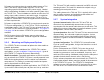
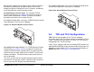
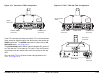
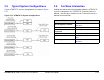
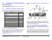
Table Of Contents
- About This Manual
- Copyright
- Proprietary Material
- Quality Certification
- Regulatory Status
- Conventions
- Symbols Used
- Warranty Information
- Introduction
- Product Description
- Routine Operation
- 3.1 Chapter Overview
- 3.2 Overview of Controls, Indicators, and Connectors
- 3.3 Preparing for Operation
- 3.4 Using the STRATA TX Screens
- 3.5 TXU and/or TCU Monitoring Operations
- 3.5.1 Using the Monitor Screens in MPEG Output Mode
- 3.5.2 Using the Monitor Screens in Ext IF Input Mode
- 3.5.3 Using the Monitor Screens in COFDM - IF Mode
- 3.5.4 Using the Monitor Screens in COFDM ASI In Mode
- 3.5.5 Using the Monitor Screens in Analog - IF Mode
- 3.5.6 Using the Monitor Screens in DVB-S Mode
- 3.6 TXU and/or TCU Control Operations
- 3.7 Front Panel vs. STRATA TX Configurator Settings
- Table 3-1: Front Panel vs. Configurator Settings
- Troubleshooting
- Channels & Frequencies
- A.1 Appendix Overview
- A.2 Initial Factory Presets
- A.2.1 3.4 to 3.8 GHz Channel Plan
- A.2.2 4.4 to 5.0 GHz Channel Plan
- A.2.3 6.4 to 7.1 GHz Channel Plan
- A.2.4 6.9 to 7.5 GHz Channel Plan
- A.2.5 7.4 to 8.0 GHz Channel Plan
- A.2.6 7.8 to 8.5 GHz Channel Plan
- A.2.7 8.2 to 8.9 GHz Channel Plan
- A.2.8 10.0 to 10.7 GHz Channel Plan
- A.2.9 10.5 to 11.2 GHz Channel Plan
- A.2.10 10.8 to 11.5 GHz Channel Plan
- A.2.11 12.7 to 13.25 GHz Channel Plan
- Glossary
- Specifications

Product Description 2-7STRATA TX Operator’s Guide/Tech Ref Manual
2.3 System Components
This section will provide more details about each the
components of a STRATA TX System:
•STRATA TXU
• STRATA TCU
•STRATA ACU
• STRATA Remote Control Panels
For details on connections between the STRATA TX System
components, refer to the “Installation” chapter (part of the
STRATA TX Technical Reference Manual only).
2.3.1 STRATA TXU
The TXU (See Figure 2-6) always contains an IF/RF module that
accepts either a 70 MHz COFDM, FMT IF, or external 70 MHz
input signal and up-converts these signals to the required RF
band. The RF frequency synthesizer circuit included in the IF/RF
unit, in conjunction with the command and control power supply
module, provides the means to channelize RF video and audio
signals in the TX System RF band.
The TXU, with either an analog (FMT) or digital (MPEG/COFDM)
module, is integrated in the same housing as the HPU
components. This provides the ability to incorporate high RF
power output (12 watts of saturated RF power) into a single
analog or digital transmitter assembly.
Standard U.S. FCC band plans, as well as customer-created
channel plans, may be customized using the STRATA TX
Configurator software.
Figure 2-6: STRATA TXU
As noted previously, the TXU may also include either an MPEG/
CODFM or FMT module (but not both), in which case the TXU
serves as a stand-alone digital or analog video microwave
transmission system.
2.3.2 STRATA TCU
The TCU (See Figure 2-7 on page 2-8) may contain either
analog or digital or both analog and digital video modulation
modules. Where an application might initially employ only
analog video transmission but expects to migrate to dual,
switchable, analog and digital operation, the TCU may be
upgraded to add the MPEG/COFDM module to add this
capability.