
User Manual
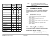
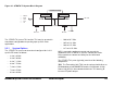
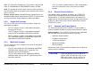
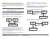
Table Of Contents
- About This Manual
- Copyright
- Proprietary Material
- Quality Certification
- Regulatory Status
- Conventions
- Symbols Used
- Warranty Information
- Introduction
- Product Description
- Routine Operation
- 3.1 Chapter Overview
- 3.2 Overview of Controls, Indicators, and Connectors
- 3.3 Preparing for Operation
- 3.4 Using the STRATA TX Screens
- 3.5 TXU and/or TCU Monitoring Operations
- 3.5.1 Using the Monitor Screens in MPEG Output Mode
- 3.5.2 Using the Monitor Screens in Ext IF Input Mode
- 3.5.3 Using the Monitor Screens in COFDM - IF Mode
- 3.5.4 Using the Monitor Screens in COFDM ASI In Mode
- 3.5.5 Using the Monitor Screens in Analog - IF Mode
- 3.5.6 Using the Monitor Screens in DVB-S Mode
- 3.6 TXU and/or TCU Control Operations
- 3.7 Front Panel vs. STRATA TX Configurator Settings
- Table 3-1: Front Panel vs. Configurator Settings
- Troubleshooting
- Channels & Frequencies
- A.1 Appendix Overview
- A.2 Initial Factory Presets
- A.2.1 3.4 to 3.8 GHz Channel Plan
- A.2.2 4.4 to 5.0 GHz Channel Plan
- A.2.3 6.4 to 7.1 GHz Channel Plan
- A.2.4 6.9 to 7.5 GHz Channel Plan
- A.2.5 7.4 to 8.0 GHz Channel Plan
- A.2.6 7.8 to 8.5 GHz Channel Plan
- A.2.7 8.2 to 8.9 GHz Channel Plan
- A.2.8 10.0 to 10.7 GHz Channel Plan
- A.2.9 10.5 to 11.2 GHz Channel Plan
- A.2.10 10.8 to 11.5 GHz Channel Plan
- A.2.11 12.7 to 13.25 GHz Channel Plan
- Glossary
- Specifications

Product Description 2-4STRATA TX Operator’s Guide/Tech Ref Manual
Power Options The STRATA TX System configurations
operate on +28 VDC power, supplied externally. This DC power
can be supplied by the optional STRATA ACU, or from another
DC power source. Contact your Sales Representative for the
latest details.
Note
A TCU and TXU are defined as being “co-located”
when the TXU and TCU are physically separated
by not greater than 6 feet.
If the TXU and TCU are co-located, power must be supplied to
each unit through their individual power connectors from the
same power source. See Figure 2-2. Do not use DC on coax to
power the TXU or TCU when the units are co-located.
Figure 2-2: Powering the TXU and TCU Independently
If your installation calls for separating the TXU and TCU, the
TXU is powered by DC supplied by the TCU or the TCU is
powered by DC supplied by the TXU. The DC power is
superimposed on the coaxial cable connected between the units.
See Figure 2-3 and Figure 2-4.
The DC input voltage to the unit co-located with the DC power
supply must be greater than +24 VDC.
STRATA
TCU
DC Power (+28 V)
STRATA
TXU
Branched
Power Cable
Refer to the “Installation” Chapter on page 6-1 (part of the
STRATA TX Technical Reference Manual only) for additional
information.
For those applications that use a TCU in a standalone mode, i.e.,
to generate ASI or DVB-S signals, DC power from the TCU to
the TXU or from the TXU to the TCU cannot be used.
Figure 2-3: Powering the TXU from the TCU
Figure 2-4: Powering the TCU from the TXU
STRATA
TXU
STRATA
TCU
DC Power (+28 V)
Up to 600 ft.
(180 m)
Coax
Power
Cable
STRATA
TCU
STRATA
TXU
DC Power (+28 V )
Coax
Up to 600 ft.
(180 m)