
Specifications


MDS 05-4055A01, Rev. A MDS entraNET 900 System Guide 105
6.1 INSTALLATION
This section provides tips for selecting an appropriate site, choosing an
antenna system, and reducing the chance of harmful interference.
6.1.1 General Requirements
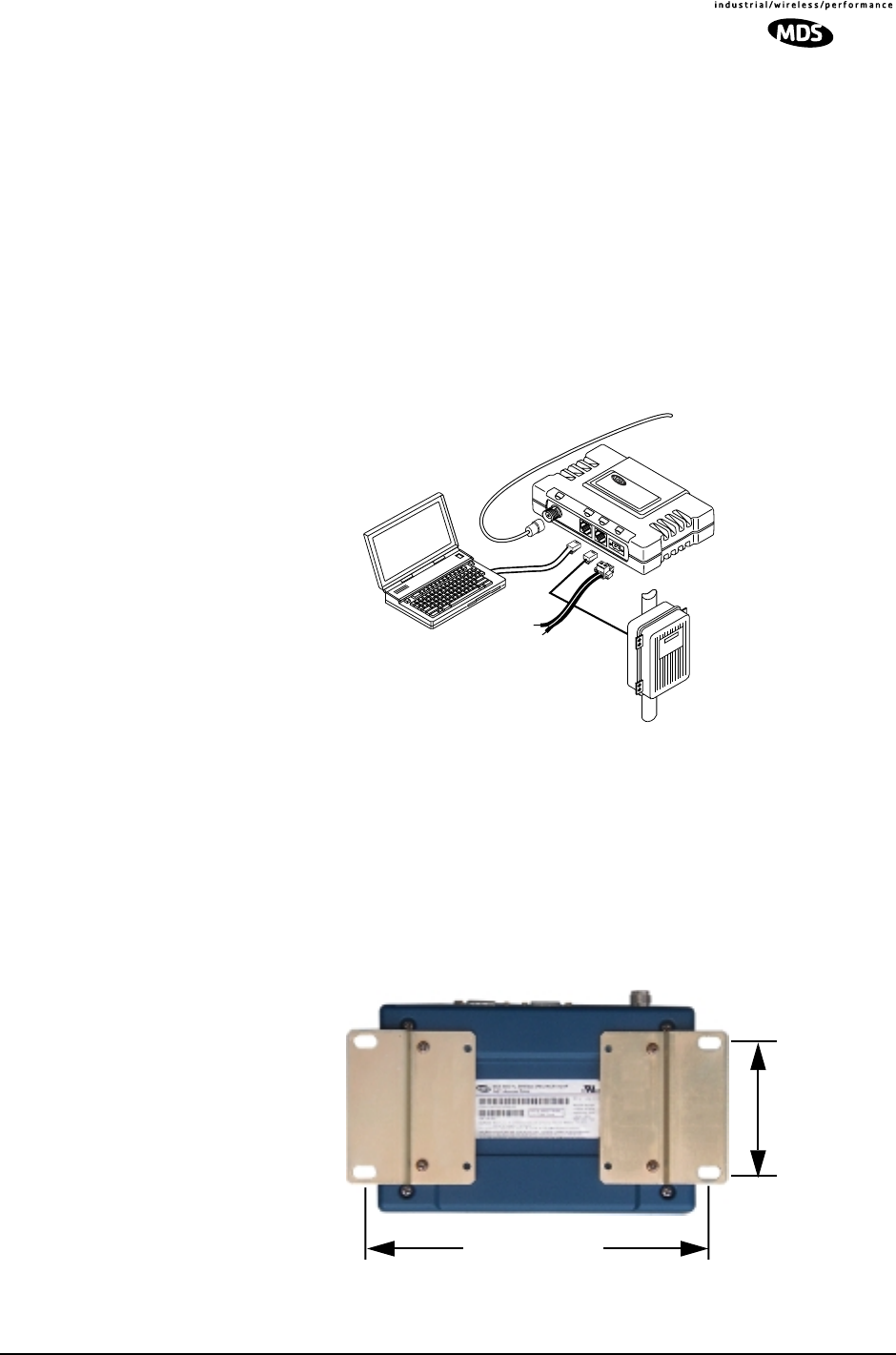
There are three main requirements for installing transceiver—adequate
and stable primary power, a good antenna system, and the correct inter-
face between the transceiver and the data device. Figure 6-1 shows a
typical Remote installation.
Invisible place holder
Figure 6-1. Typical Transceiver Installation (Remote Shown)
Mounting Dimensions
Figure 6-2 shows the dimensions of the AP transceiver with mounting
brackets attached. Figure x shows the same view for a Remote trans-
ceiver.When mounting entraNET transceivers, choose a location that
provides easy access to the connectors on the end of the radio and an
unobstructed view of the LED status indicators.
Invisible place holder
Invisible place holder
.
Figure 6-2. Mounting Bracket Spacing—Access Point
C
O
M
2
P
W
R
L
I
N
K
C
O
M
1
POWER SUPPLY
6–30 VDC @ 8 Watts
Negative Ground Only
COMPUTER
W/TERMINAL
EMULATOR
TRANSCEIVER
LOW-LOSS FEEDLINE
TO
ANTENNA SYSTEM
SERIAL OR
ETHERNET RTU
2.75˝ (7 cm)
7.25˝ (18.4 cm)