MDS entraNET Access Point Serial Remote Ethernet Remote Extended Range IP Networking Transceivers MDS 05-4055A01, Rev. A OCTOBER 2003 System Guide Microwave Data Systems Inc.
Contents 1 INTRODUCING THE entraNET SYSTEM ................... 1 1.1 PRODUCT DESCRIPTION................................................................................................... 3 1.1.1 Model Offerings .......................................................................................................................... 5 1.2 APPLICATIONS .................................................................................................................... 5 1.2.1 Long Range Wireless LAN ........
Ethernet Remotes ..........................................................................................................................21 Serial Remotes ..............................................................................................................................22 3 AP MANAGEMENT .................................................. 23 3.1 INTRODUCTION ................................................................................................................ 25 3.1.1 Menu Structure .
Remote Database Menu ................................................................................................................54 Endpoint Database Menu ..............................................................................................................55 Access Point Database Menu ........................................................................................................56 3.8 STATISTICS/EVENT LOG ................................................................................
5.1.4 Point-to-Multipoint Serial-to-Serial Application Example ........................................................100 5.1.5 Mixed Mode Application Example ..........................................................................................101 Operation and Data Flow .............................................................................................................101 6 INSTALLATION ....................................................... 103 6.1 INSTALLATION ............................
Copyright Notice This publication is protected by U.S.A. copyright law. Copyright 2003, Microwave Data Systems, Inc. All rights reserved. ISO 9001 Registration Microwave Data Systems adheres to the internationally-accepted ISO 9001 quality system standard. Related Materials on the Internet Data sheets, frequently asked questions, case studies, application notes, firmware upgrades and other valuable information are available on the MDS Web site at www.microwavedata.com. About Microwave Data Systems Inc.
The transceiver has been recognized for use in these hazardous locations by two independent agencies —Underwriters Laboratories (UL) and the Canadian Standards Association (CSA). The UL certification for the transceiver is as a Recognized Component for use in these hazardous locations, in accordance with UL Standard 1604. The CSA Certification is in accordance with CSA STD C22.2 No. 213-M1987.
K LIN R PW M2 CO M1 CO N LA 1 INTRODUCING THE entraNET SYSTEM 1 Chapter Counter Reset Paragraph Contents 1.1 PRODUCT DESCRIPTION ...................................................... 3 1.1.1 Model Offerings ..........................................................................5 1.2 APPLICATIONS ........................................................................ 5 1.2.1 Long Range Wireless LAN .........................................................5 Antenna Placement ......................
K LIN R PW M2 CO M1 CO N LA 2 MDS entraNET 900 System Guide MDS 05-4055A01, Rev.
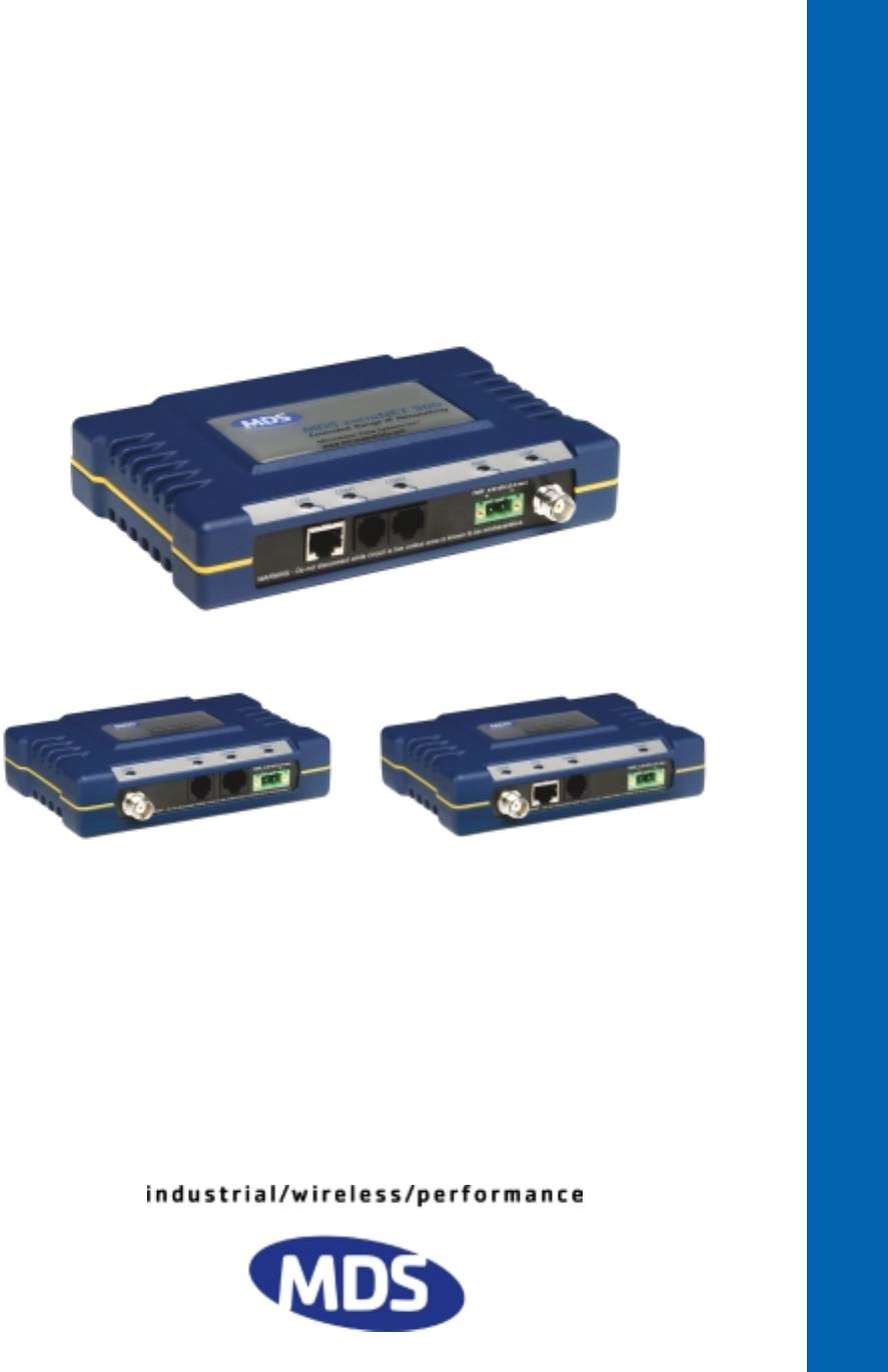
1.1 PRODUCT DESCRIPTION This manual presents installation and operating instructions for the MDS entraNET 900 system. The manual is for use by those who will install, operate, and perform basic maintenance on the radio system. The entraNET system is an easy-to-install wireless solution supporting long range Serial and Ethernet data transmission at speeds up to 106 kbps. The system includes an Access Point (AP) transceiver and two types of Remote transceivers—Serial or Ethernet.
apply power, set a few operating parameters and you are done. No license is required for operation in the U.S.A., Canada, and many other countries. Check the regulations in your country before placing the units on the air. Secure Operation Network security is a vital issue in today's wireless world. The MDS entraNET system provides multiple tools to help you build a network that minimizes the risk of eavesdropping and unauthorized network access.
• Low Power Consumption—Sleep and Shutdown modes to enable solar-powered operation • Single Radio Repeater (Available soon—Contact MDS for information)—Store & Forward capability to extend the range of a link or to work around obstructions without the expense and complexity of a traditional repeater.
more associated Remote units, as shown in Figure 1-2 on Page 6. A LAN provides communications between a central WAN/LAN and Remote Ethernet endpoints. Ethernet Remotes can support only one Ethernet endpoint each. The operation of the radio system is “transparent” to the computer equipment it is connected to. That is, the system behaves just as it would in a hardwired arrangement, with respect to data format and integrity.
pendent and the transceiver provides seamless simultaneous operation as shown in Figure 1-3. Invisible place holder Serial Remote RTU EIA-232 LINK COM 1 COM 2 PWR SCADA Host Modbus/IP Access Point LINK Serial Remote PWR HUB HUB 1 COM 2 COM EIA-232 LAN Serial Device LINK COM 1 COM 2 PWR WAN Serial Polling Converter ROUTER Ethernet Remote TCP/IP HUB HUB Ethernet Device LINK ETH COM 1 PWR PC Running NetView SCADA Host Total Flow Figure 1-3.
for EIA-232 signaling. The COM2 port supports standard EIA-232 signaling and acts as a data-communications equipment device (DCE). NOTE: Several previous MDS-brand products contained signal lines on their interface connectors that are not used or required on entraNET units. Consult the legacy equipment manual(s) for interface pinout information and connect only the required pins. Supplement legacy wireless network with IP services MDS entraNET 900 serial Remotes support most polled protocols.
Table 1-2. Security Risk Management Security Risk The MDS entraNET 900 Solution Denial of service, where Remote radios could be reconfigured with bad parameters bringing the network down. ✓ ✓ ✓ Remote login Local console login Disabled HTTP & Telnet to allow only local management services ✓ 900 MHz FHSS does not talk over the air with standard 802.
Table 1-3. Accessories Accessory Description AC Power Adapter Kit A small power supply module designed for continuous service. UL approved. Input: 120/220; Output: 13.8 Vdc @ 2.5 A OmniDirectional Antennas Rugged antennas well suited for use at Access Point installations. Consult with your factory Sales Representative for details Contact factory Yagi Antenna (Directional) Rugged antennas well suited for use at Remote installations. Consult with your factory Sales Representative for details.
K LIN R PW M2 CO M1 CO N LA 2 TEST SETUP AND EVALUATION 2 Chapter Counter Reset Paragraph Contents 2.1 INTRODUCTION .................................................................... 13 2.1.1 Connector Overview .................................................................13 2.2 STEP 1—CONNECT THE ANTENNA PORTS....................... 15 2.3 STEP 2—MEASURE & CONNECT DC POWER ................... 16 2.4 STEP 3—CONFIGURE THE TRANSCEIVERS ..................... 17 2.4.1 Access Point Configuration .....
K LIN R PW M2 CO M1 CO N LA 12 MDS entraNET 900 System Guide MDS 05-4055A01, Rev.
2.1 INTRODUCTION Prior to field installation, it is recommended that the radio system be set up in a controlled environment to become familiar with its operation. A tabletop network can be established to verify the basic operation of the system and allow tests of various network designs and configurations. Such a test can be performed with any number of radios. This section describes the hardware setup and software configuration needed for a tabletop test.
Invisible place holder LAN ◆ 10-Base-T ◆ IP/Ethernet Port ◆ IP Address: 192.168.0.1 COM1 ◆ DCE (Console/Terminal only) ◆ 19,200 bps/8N1 ◆ No Handshaking ◆ RS/EIA-232 ANTENNA ◆ 50Ω TNC ◆ +30 dBm/1W Out (Max.) ◆ –30 dBm Input (Max.) PRIMARY POWER ◆ 6–30 Vdc (800 ma @ 13.8 Vdc) ◆ Negative Ground COM2 ◆ DCE (Connects to serial data equip.) ◆ 9,600 bps/8N1 ◆ Full Handshaking ◆ RS/EIA-232 Figure 2-1.
Invisible place holder ANTENNA ◆ 50Ω TNC ◆ +30 dBm/1W Out (Max.) ◆ –30 dBm Input (Max.) COM1 ◆ DCE (Console/Terminal only) ◆ 19,200 bps/8N1 ◆ No Handshaking ◆ RS/EIA-232 PRIMARY POWER ◆ 6–30 Vdc (600 ma @ 13.8 Vdc) ◆ Negative Ground COM2 ◆ DCE (Connects to serial data equip.) ◆ 9,600 bps/8N1 ◆ Full Handshaking ◆ RS/EIA-232 Figure 2-3. Serial Remote Interface Connectors 2.2 STEP 1—CONNECT THE ANTENNA PORTS Figure 2-4 is a drawing of a tabletop arrangement.
NOTE: It is very important to use attenuation between all units in the test setup. The amount of attenuation required will depend on the number of units being tested and the desired signal strength (RSSI) at each transceiver during the test. In no case should a signal greater than –30 dBm be applied to any transceiver in the test setup. A transmit RF power output level of +20 dBm is recommended. (See “Radio Configuration Menu” on Page 40.) 2.
2.4 STEP 3—CONFIGURE THE TRANSCEIVERS 2.4.1 Access Point Configuration The Access Point must be configured first, as Remote transceivers depend on the AP’s beacon signal to achieve a “connected” (linked) state. To configure the Access Point, connect a PC with the radio’s COM1 port and establish a terminal session (i.e., HyperTerminal) using the following data parameters: 19200 bps, 8 bits, no parity, one stop bit (8N1), flow control disabled, VT100 emulation.
5. Repeat Steps 1–4 for any other AP units in your radio system. NOTE: The Management System supports the use of “configuration scripts” to aid in uniformly configuring multiple transceivers. This time-saving technique is detailed in Using Configuration Scripts, on Page 71. AP Configuration Settings Table 2-1 provides a listing of key AP operating parameters, their default settings, and values or range.
Invisible place holder Remote R PW M2 CO M1 CO K LIN COM1 Port PC Running Terminal Session (19,2000 bps, 8N1) Figure 2-7. Remote Configuration Setup Log in Follow these steps to login to the radio. 1. Press a few ENTER keystrokes to receive the entranet> prompt. (The COM1/ETH LED blinks to indicate data communication.) 2. At the entranet> prompt, type login. Press ENTER . 3. At the next prompt, enter username (default username is admin). Press ENTER . 4.
This concludes the basic setup of a Remote radio. A full listing of Remote programming commands is given in CHAPTER-4 REMOTE RADIO MANAGEMENT beginning on Page 79. With all units connected, you are ready to connect data devices to the transceivers so that their operation can be tested over the wireless network. 2.5 STEP 4—CONNECT TERMINAL EQUIPMENT This step describes connection of external data equipment to the Remote radio. Verify that your transceiver is capable of supporting your devices.
• LAN/ETH (Ethernet units)—On or blinks intermittently • COM2—Blinks to indicate data communications Table 2-2 provides details on the LED functions for Remotes and AP radios. Table 2-2.
Invisible place holder PC RUNNING PING UTILITY ACCESS POINT CROSS-OVER CABLE ETHERNET REMOTE LINK ET H CO M1 LA N CO M1 CO M2 PW R ETH PORT PW R LINK LAN PORT STRAIGHT THROUGH CABLE ETHERNET ENDPOINT (Device Being Pinged) Figure 2-8. Ping Test Setup (To test connectivity between an AP and an Ethernet Endpoint) Serial Remotes To check connectivity with Serial Remotes, refer to Serial Data Port Configuration Menu (Local Serial-to-Remote Serial or IP-to-Local Serial), on Page 44.
K LIN R PW M2 CO M1 CO N LA 3 AP MANAGEMENT 3 Chapter Counter Reset Paragraph 3.1 INTRODUCTION .................................................................... 25 3.1.1 Menu Structure ........................................................................25 3.1.2 Differences in the User Interfaces ............................................28 3.1.3 Accessing the Embedded Management System .....................29 3.1.4 Navigating the Menus ..........................................................
Remote Management Menu ..........................................................52 Remote Database Menu................................................................54 Endpoint Database Menu ..............................................................55 Access Point Database Menu ....................................................................56 3.8 STATISTICS/EVENT LOG ...................................................... 56 3.8.1 3.8.2 3.8.3 3.8.4 3.8.5 COM1 & 2 Serial Data Statistics Menus ..
3.1 INTRODUCTION The MDS entraNET 900 AP is equipped with an embedded management system that is accessible through various data interfaces. These include the COM1 (serial) port and the LAN (Ethernet) port. Essentially the same capabilities are available through any of these paths. To access any of the interfaces, you must enter a valid password and username. Future firmware releases for the transceiver will also support SNMP-based management tools such as Microwave Data Systems’ NETview MS™.
26 MAIN MENU—Diagram 1 of 2 MDS entraNET 900 System Guide Talkback Timeout Execute Changes Talkback Enable Remote ComPort Remote UnitID • Spacebar used to make some menu selections Auth Trap Enable Trap Managers v3 Password Mode Trap Version SNMP Mode v3 Priv Password NOTES • Chart shows top-level view only. The pages that follow provide detailed screen-by-screen explanations.
MDS 05-4055A01, Rev. A MDS entraNET 900 System Guide Packets Dropped Receive Errors Lost Carrier Detected Packets In Bytes In Packets Out Number of Remotes List of Remotes NOTES • Chart shows top-level view only. The pages that follow provide detailed screen-by-screen explanations.
3.1.2 Differences in the User Interfaces There are slight differences in navigation between Telnet, Terminal and Web interfaces, but for the most part, the content of screens will be the same. There area few differences in capabilities, as the communications tool is driven by limitations of the access channel. Below are samples of the Starting Information Screen as seen through a terminal session and a web browser. Invisible place holder Figure 3-3.
3.1.3 Accessing the Embedded Management System The menu-based management system provides access to view and configure many unit parameters and provides you with basic diagnostic and maintenance tools. There are several ways to gain access to the entraNET Management System. • Terminal-Emulator—Use a terminal emulator program on your PC, such as HyperTerminal, connected directly to the MDS entraNET 900 COM1 port via a serial cable.
Procedure with Terminal Emulator a. Connect a computer’s serial communications port to the transceiver’s COM1 Port connector. b. Launch a terminal emulator program, such as HyperTerminal, on the computer. Configure it to 19,200 bps data rate, 8-bit characters, no parity, one stop bit, and no flow-control. Use ANSI or VT100 emulation. c. Press the ENTER key. A login screen will be displayed that requires a user name and password to access the Management System.
d. A login screen will be displayed that requires a user name and password to access the Management System. Note that the default entries are made in lower case. (Defaults: user = admin; password= admin) e. The transceiver responds with the startup menu screen. (See Figure 3-6 on Page 32.) NOTE: If the default address of 192.168.1.1 does not work, use the terminal-emulator procedure to communicate with the unit through the COM1 port.
3.1.5 Logging Out of the entraNET Management System NOTE: To maintain security, it is best to formally log-out of the entraNET Management System. If you do not log out, the session will be terminated after 10 minutes of inactivity. Via Web Browser To logout of the entraNET MS with a Web browser, click on the “Logout” listing in the left hand frame of the browser window. The right-hand frame will change to a logout page. Follow the instructions on this Web page.
played, an “A)” will appear to the left of the Device Status field as seen in Figure 3-6. Pressing the “A” key on your keyboard will take you directly to the “Current Alarms” screen. • Connected Remotes— Current number of Remote radios connected to the AP. • Location—User definable string used to help identify the unit. • Serial Number—Unique identifier for this device. It must be provided to purchase Authorization Keys to upgrade unit capabilities. (See “Authorization Keys Menu” on Page 78.
• Local Serial Configuration—Tools to configure the COM1 and COM2 serial port of the AP. (See “Serial Data Port Configuration Menu (Local Serial-to-Remote Serial or IP-to-Local Serial)” on Page 44) • Remote Serial Gateway—Contains tools to configure data connections to the Remote transceiver serial ports. • Security Configuration—Tools to configure the security services available with the transceiver environment.
Invisible place holder Figure 3-8. Network Configuration Menu From Access Point This menu is subdivided into six sections as follows: • IP Configuration—The transceiver’s IP address and similar parameters. • Wireless MAC Configuration—Parameters for the Media Access Control (MAC)wireless protocol. • Mobility Configuration—Parameters that govern the behavior of handoffs. • SNMP Configuration (Available soon)—Details that control the operation of SNMP.
3.3.2 IP Configuration Menu Figure 3-9. IP Configuration Menu • IP Address (User Review Recommended)—Essential for connectivity to the MDS entraNET 900 MS via the LAN port and over the air. Enter any valid IP address that will be unique within the network. [192.168.1.1] CAUTION: Changing this value in the transceiver while you are communicating with it over the network, will cause a loss of communication with the transceiver. Communication will need to be re-established using the new IP address.
3.3.3 Wireless MAC Configuration • Radio Net(work) Address (User Review Required)—ID of the network of which this unit will be a part. Essential for connection of Remotes to the Access Point in the entraNET network. [Not Programmed] • X Address—”Extended Address” used for store and forward operation and in installations with multiple APs supporting mobility. Net Address and X Address pairs must be unique. For single AP networks, this parameter is not used.
• BSP Routing Enable—This parameter enables intra-cell and routing of Basic Serial Protocol packets. • IAPP Enable—This parameter enables Inter-Access Point Protocol which allows Access Points to pass payload data over the Ethernet LAN. • Unit Update Enable—This parameter allows the Access Point to immediately send out an IAPP update when a Remote connects or disconnects. SNMP Configuration (Figure 3-10) The current release of transceiver firmware does not support SNMP management.
• SNMP v3 Priv Password—Privacy password stored in flash memory. Used when the SNMP Agent is managing passwords locally (or initially for all cases on reboot). This is the SNMPv3 used for privacy (DES encryption). The password string can be between 8 and 30 alpha-numeric characters. [Manager, Local; Local] • SNMP Mode—Current state of the SNMP agent. [Enable/Disabled, v1-only, v2-only, v3-only, v3-only, v1-v2, v1-v2-v3; Disabled] • Trap Version—Set version to be used with traps.
• Bridge Forward Delay—This value decides how long a bridge will spend in the “learning” and “listening” states. Traffic will begin forwarding through the bridge after 2 * Forward Delay. 3.4 CONFIGURING RADIO PARAMETERS There are two primary data layers in the MDS entraNET 900 network— radio and data. The data layer is dependent on the radio layer to work properly. The Radio Configuration Menu, is the primary radio menu. There is also a secondary menu, the Skip Zone Options Menu. 3.4.
• Broadcast Repeat Count—Sets the number of times point-to-multipoint messages will be transmitted by the AP. Higher values provide more reliability but also more over-the-air congestion. • Unicast Retry Count—Sets the maximum number of attempts that will be made to deliver point-to-point messages.Higher values provide more reliability but also more over-the-air congestion. • Skip Zones (Editable at Access Point Only)—Display of current utilization of zones. Each zone consists of 16 RF channels.
3.5 CONFIGURING THE SERIAL INTERFACES 3.5.1 Overview To understand the operation of the radio system, it may be helpful to visualize the AP and the Remotes as being in a single box, with the AP ports on one side and all of the Remotes on the other (see Figure 3-14). In practice, the units are typically separated by considerable distances, but viewing them as a single unit will be helpful for this discussion.
To configure IP-to-remote serial services, use the Remote Serial Gateway menu (Figure 3-20 on Page 48). To configure local serial-to-remote-serial or IP-to-local-serial services, use the Local Serial Configuration menu Figure 3-15 on Page 44. Most polled protocols will be best served by UDP services as the protocol itself has built-in recovery mechanisms (error-correction).
3.5.2 Serial Data Port Configuration Menu (Local Serial-to-Remote Serial, or IP-to-Local Serial) Figure 3-15. COM1/2—Local Serial Configuration Menu • Port Status—Defines whether the serial COM1/2 port is enabled or disabled to pass data. • Serial Configuration Wizard—Tool for configuration of the serial ports using a step-by-step process. When the wizard is started, you may choose between beginning the step-by-step process, or simply viewing the current settings (see Figure 3-16). Figure 3-16.
The Serial Configuration Wizard consists of a series of screens used to set all of the parameters needed for proper operation of the serial port(s). Each screen provides text that will help you in choosing selections. If you choose “View Current Settings,” you will see a summary screen of the serial configuration settings (Figure 3-17). Here, you may either select the letter of an item to change, or exit the configuration wizard. Invisible place holder Figure 3-17.
The following text explains the key settings for the serial configuration menus. • Port Status—Enable/Disable the serial data port. NOTE: Setting the COM1 port to Enable prevents access of the entraNET Management System (MS) through this port. However, the entraNET MS can still be accessed via Telnet or browser through the LAN port. To restore the COM1 port to support Management System access, connect a terminal to the port and enter an escape sequence to reset it the console mode.
• Inter-Packet Delay— Number of characters that represent the end of a message (inter-character time-out). A transceiver receiving data through the serial port will send an end-of-message signal to the remote end. MODBUS defines a “3.5-character” parameter. [0–1,000; 0] 3.5.3 Remote Serial Gateway Configuration (IP-to-Remote Serial) The serial gateway controls the behavior of all Remote radios from the perspective of IP encapsulation.
host) the RSG will revert to its configured IP address and port for upstream data destined for an IP host. • RSG Entries—Allows entry of key RSG parameters including Unit ID, COM Port setting, Mode, and Local IP Port selection. This screen is shown in Figure 3-20. • Remote Serial Wizard—Tool that will assist you in adding/changing a configuration to your Remote Serial Gateway entries. Invisible place holder Figure 3-20.
3.6 SECURITY CONFIGURATION There are many options for assisting you in providing secondary security for your transceivers and the network. These options start with controlling remote access to the network via Telnet, Web Browser, and SNMP. Other areas include multiple levels of encryption and MD5-level security for HTTP connections. 3.6.
• HTTP Access—Prevents remote access through HTTP (Web browser) on Port 80 [Enabled/Disabled; Disabled] • Telnet Access—Prevents remote access through Telnet sessions on Port 23 [Enabled, Disabled; Enabled] • SNMP Mode— Prevents remote access through SNMP commands on Port 161 [Enabled, Disabled; Enabled] • Approved Remotes List (Menu)—Presents a menu where the creation and management of Remote units allowed to communicate with the AP is performed.
Figure 3-22. Approved Remotes List Menu • Add Remote—Enter the serial number of Remote. [ten-digit number] • Delete Remote—Enter serial number of Remote to be deleted. • • • • • • For security purposes, you should delete a deprovisioned or stolen radio. Previous Page—Returns you to the last page viewed within the Approved Remotes Menu. Add Connected Remotes—Adds all currently connected Remotes (1-255) to the approved Remote list. Alternatively, you can enter each Remote serial number manually.
which is related to Remotes, is not actually sent to Remotes, but is stored in a local database at the AP. Invisible place holder Figure 3-23. Wireless Network Menu • Database Timeout—The time, in minutes, before a database entry expires. Remotes must be “refreshed” through a handshake process to stay in the database of connected Remotes. This allows decommissioned or faulty radios to fall out of the database to maximize efficiency if the entries are not needed.
Figure 3-24. Remote Management Menu When “Manage Selected Remote” is chosen, the screen shown in Figure 3-25 appears. It contains several items that are used to set the characteristics of Remote radios in the network. Invisible place holder Figure 3-25. Manage Selected Remote Menu • Device Information—Shows hardware and software version information, including bootloader version. • Network—Tool for control of the Ethernet port (enable/disable).
• Serial Configuration—Tool for configuring COM1/2 parameters, including: Port Mode, Baud Rate, Byte Format, Seamless Mode, Interpacket Delay, and Buffer Size. • Statistics—Presents packet throughput and retry data for the selected Remote • Remote Reprogramming—Menu for sending new firmware images and specifying the image that will be active upon re-boot. Remote Database Menu The Remote Database Menu (Figure 3-26) shows several parameters related to the connected Remotes.
• RX Pkts—Number of packets received from this Remote. • Num EPs—Number of endpoints connected to this Remote. Endpoint Database Menu The Endpoint Database Menu (Figure 3-27) shows all non-entraNET 900 Ethernet devices that are known to the transceiver and is equivalent to the ARP table of IP devices. The list shows endpoint MAC and IP addresses, as well as packet exchange data.
• RxPkts—Over-the-air data packets received by the transceiver. and passed on to the endpoint device. Access Point Database Menu The Access Point Database Menu (Figure 3-28) provides a listing of all Access Points contained in the wireless network and includes details about each unit. Invisible place holder Figure 3-28. Access Point Database • Serial Number—Factory-assigned serial number for the Access Point. • IP Address—IP Address of the Access Point.
Invisible place holder Figure 3-29. Statistics/Event Log Menu (Main Screen) • COM1/2 Serial Data Statistics—These screens show bytes in/out for the COM1/2 ports • Remote Serial Gateway Statistics—Shows Unit ID, status and throughput data for connected Remotes. • Ethernet/Wireless Packet Statistics—Shows vital data on packets and bytes in/out of the radio, errors detected, and lost Ethernet carriers.
3.8.1 COM1 & 2 Serial Data Statistics Menus (See Figure 3-30) Invisible place holder Figure 3-30. Com1/2 Data Statistics Menu • Bytes in on port—Number of bytes received by the transceiver through the serial interface • Bytes out on port—Number of bytes transmitted by the transceiver through the serial interface • Bytes in on socket—Number of bytes received by the transceiver through the IP socket • Bytes out on socket—Number of bytes transmitted by the transceiver through the IP socket. 3.8.
Figure 3-31. Serial Data Statistics Screen (Verify as latest screen) (Both COM1 and COM2 are shown, as applicable) • UnitID—The unit ID of the connected Remote. • Com—Communication port being monitored (COM1 or COM2). • IP Port—IP port associated with the listed device. • State—State of the AP’s server for this Remote. [Listening; Connected] 3.8.
Figure 3-32. Sample Packet Statistics Menu (Ethernet shown) Wireless Packet Statistics • Packets received—Over-the-air data packets received by this unit • Packets sent—Over-the-air data packets sent by this unit. • Bytes received—Over-the-air data bytes received by this unit. • Bytes sent—Over-the-air data bytes sent by this unit. • Packets dropped—Received packets dropped as a result of a lack of buffers. • Receive errors—Packets that do not pass CRC.
3.8.4 Radio Packet Statistics The previous screen dealt with Ethernet-related information. The Radio Packet Statistics menu (Figure 3-33) contains statistics that relate directly to over-the-air transmission of data. It provides valuable insight into the quality of the RF link between entraNET units with respect to the handling of data packets. Invisible place holder Figure 3-33. Radio Packet Statistics Menu • Overflow—TX packets with “lcp buffer overflow” data responses.
events. These will cause the unit to enter an “alarmed” state and the POWER LED to blink until the condition is corrected. All events are stored in the Events Log that can hold about 5000 entries. Table 3-1.
Invisible place holder Figure 3-35. View Event Log Menu • Clear Log—Purges the log of all stored events. TIP: Save your Event Log before choosing to clear it in order to retain potentially valuable troubleshooting information. (See “Upgrading the AP’S Firmware” on Page 67 for an overview on how to transfer files from the transceiver to a computer on the network using TFTP.
3.9 DEVICE INFORMATION MENU Figure 3-36 is the menu/screen that displays basic administrative data on the unit to which you are connected. It also provides a date and time display, Console Baud Rate setting, and user- specific parameters under the Device Names selection. Invisible place holder Figure 3-36. Device Information Menu • Model Number (Display only) • Serial Number (Display only) • Uptime (Display only)—Elapsed time since powering up the unit.
Device Names Menu Figure 3-37. Device Names Menu • Device Name—Device Name, used by the transceiver as the “Realm” name for network security and menu headings. • Contact—User defined; appears on this screen only. • Location—User defined; appears on this screen only. • Description—User defined; appears on this screen only. 3.
Figure 3-38. Maintenance/Tools Menu 3.10.1Reprogramming Menu The AP transceiver has two copies of the firmware (microprocessor code) used for the operating system and applications. One copy is “active” and the second one is standing by, ready to be used. You can upload a new release into the inactive position and place it in service whenever you desire. Figure 3-39. Reprogramming Menu (Shown with “Image Copy” Selected) • TFTP Host Address—IP address of the host computer from which to get the file.
• Firmware Filename—Name of file to be received from the TFTP server. [Any 40-character alphanumeric string] Verify that this corresponds to the TFTP directory location. May require sub-directory, for example: entranet/bkrfto-1_0_0.gpk. • TFTP Timeout—Time in seconds the TFTP server will wait for a packet ACK (acknowledgment) from the transceiver before suspending the file transfer. [10 to 120 seconds; 10] • Retrieve File—Initiate the file transfer from the TFTP server.
• Web Browser—Connect to the transceiver using a Web browser on a local PC connected directly to the transceiver’s LAN port or associated network. Firmware images are provided free-of-charge on the MDS Web site at: www.microwavedata.com/service/technical/support Upgrading the Transceiver Firmware To install firmware by TFTP, the user will need: • A PC with a TFTP server running. (A TFTP Server is available for download from the MDS website—see below.) • The IP address of the PC running the TFTP server.
Invisible place holder REMOTE PC W/FIRMWARE FILES TFTP SERVER HUB/LAN/WAN/MAN TCP/IP ETHERNET PORT ACCESS POINT IP ADDRESS: 192.168.0.1 IP ADDRESS: 192.168.0.10.0 LAN PORT LA N CO M1 CO M2 PW R LINK AL IN M M R RA TE OG PR LOCAL PC COM1, 2, ETC. (DTE) IN 9-P SERIAL CABLE P. COM1 DA PORT A 2 (DCE) J- 1 W/R INITIATE UPLOAD FROM HERE Figure 3-41.
5. Pull the firmware file through the TFTP server into the entraNET unit. (Main Menu>Maintenance Menu>Reprogramming Menu>Retrieve File) • Status messages on the transfer are posted on the PC screen. You can cancel the transfer at any time by pressing CTRL-C. • If the transfer does not start, verify that the AP and the PC can “ping” each other. 6. Reboot the transceiver to the new firmware image to make it active. Main Menu>Maintenance Menu>Reprogramming Menu>Reboot Device 7.
• TFTP Timeout—Time in seconds the TFTP server will wait for a packet ACK (acknowledgment) from the transceiver before suspending the file transfer. [10 to 120 seconds; 10] • Retrieve File—Initiate the file transfer of the configuration file from TFTP server into the transceiver. • Send File—Initiate the file transfer from the transceiver’s current configuration file to TFTP server. NOTE: See “Upgrading the AP’S Firmware” on Page 67 for details on setting up the TFTP server.
to appear below associated parameter lines. Some of the values used in the calibration of the unit’s built-in test equipment have been deleted to reduce space. This presentation is offered as a guide to the type of information contained in the file. See “Editing Configuration Files” on Page 76 for further information. NOTE: The parameter names and the data values from the Exported Configuration File are shown in bolded text. Any description will be found below in an indented paragraph.
The contact person regarding this unit. Description: Link to Campus Server A brief general description of this unit. Location: Hollister Bldg. RM450 The physical location of this unit. Com2 Port Config: 8N1 Configuration of character size, type of parity, and number of stop bits to be used Max Remotes Allowed: 50 The maximum number of Remotes allowed to connect to this Access Point. Device Mode: Access Point Configures the unit to act as a Remote or an Access Point.
Skipped Hop Zone4: Active Skipped Hop Zone5: Active Skipped Hop Zone6: Active Skipped Hop Zone7: Active Skipped Hop Zone8: Active Skipped Hop Zone9: Active Skipped Hop Zone10: Active Firmware TFTP Host IP: 63.249.227.105 Address of the TFTP Host from which firmware images are downloaded Firmware TFTP Filename: entraNET-bkrto-3_0_0.gpk Eventlog TFTP Host IP: 192.168.1.3 Address of TFTP Host to which to send the event log Eventlog TFTP Filename: eventlog.txt Config Script TFTP Host IP: 192.168.1.
Com1 Serial Data Mode: UDP IP Protocol for COM1 data mode Com1 Serial Data Baud Rate: 9600 Baud rate for COM1 data mode Com1 Serial Data Tx IP Address: 0.0.0.0 COM1 data will be sent to this IP address Com1 Serial Data Tx IP Port: 0 COM1 data will be sent to this IP port Com1 Serial Data Rx IP Port: 0 COM1 data will be received on this IP port Com2 Serial Data Enable: enabled Com2 Serial Data Mode: UDP Com2 Serial Data Baud Rate: 9600 Com2 Serial Data Tx IP Address: 169.254.10.
SNMP Enable: disabled Enable/Disable SNMP Agent Approved Remotes List Enable: disabled Setting to enable the Approved Remotes List Encryption Enable: disabled Setting to enable over-the-air data encryption HTTP Enable: enabled Setting to enable the HTTP interface Telnet Enable: enabled Setting to enable the Telnet interface HTTP MD5 Authentication: disabled Setting to enable MD5 Digest Authentication End of Configuration File Editing Configuration Files Once a Remote unit’s operation is fine-tuned, us
• Change only the parameter values. • Capitalization counts in some field parameters. (Example: System Mode) • Comment Fields a. Edit, or delete anything on each line to the right of the comment delimiter, the semicolon (;). b. Comments can be of any length, but must be on the same line as the parameter, or on a new line that begins with a semicolon character. c. Comments after parameters included in files exported from a transceiver do not need to be present in your customized files. 3.10.
3.10.4Authorization Keys Menu Figure 3-44. Authorization Keys Menu • Authorization Key—Initiate the entering of an Authorization Key into the transceiver’s non-volatile memory. • Authorized Features—List of authorized features. In this example, MDS NETview MS is shown. This software product is intended to help users monitor system performance, configure network elements, detect faults and correct problems in the convenience of an office setting or at any other point in the network.
K LIN R PW M2 CO M1 CO N LA 4 REMOTE RADIO MANAGEMENT 4 Chapter Counter Reset Paragraph Contents 4.1 INTRODUCTION MDS 05-4055A01, Rev. A 81 4.1.1 Programming Methods Terminal Interface Mode Remote Management via the AP PC-Based Configuration Software 4.1.2 User Commands Entering Commands Command Responses 4.1.3 Minimum Remote Configuration 4.1.4 Detailed Command Descriptions 81 81 81 81 81 81 82 82 83 4.
K LIN R PW M2 CO M1 CO N LA 80 MDS entraNET 900 System Guide MDS 05-4055A01, Rev.
4.1 INTRODUCTION The configuration of Remote transceivers is performed through a PC terminal connected to the radio’s COM1 port. There are no manual adjustments or jumper settings required for configuration. This section explains how to establish a terminal session with the Remote and provides a complete list of user commands. 4.1.1 Programming Methods Terminal Interface Mode A PC program, such as HyperTerminal, may be used to provide a terminal session to enter the commands listed in Table 4-1 below.
Command Responses The transceiver supports two command response formats—standard (plain language) and a hex format that may be copied into a configuration script. If you enter 0 after a command, the command executes normally (plain language). If you enter 1 after the command, the response is reported in hex format. Hex format is useful for automated processing of response data. 4.1.
Table 4-1. Remote Commands—Quick Reference (Continued) COMMAND DESCRIPTION PROGRAM Allows a boot to the bootloader RADIO Set/display the radio configuration and status REBOOT Restart the radio’s firmware SLEEP Selects one of the low power operating modes: Sleep, Shutdown STATS Shows radio statistics VER Set/display the current version information 4.1.4 Detailed Command Descriptions HELP Lists commands supported for the current user login level.
APx= —AP units, where x = 1 to 10. Sets / displays the serial number for one of 10 approved APs with which the Remote should accept connection. A serial number of 0 is used to delete an entry and indicates the slot is not filled.
FORMAT=—Sets / displays data characters, parity, and stop bits setting of the COM port.
7E2—7 char bits, even parity, 2 stop bits 8N1—8 char bits, no parity, 1 stop bit (Default) 8N2—8 char bits, no parity, 2 stop bits 8O1—8 char bits, odd parity, 1 stop bit 8O2—8 char bits, odd parity, 2 stop bits 8E1—8 char bits, even parity, 1 stop bit 8E2—8 char bits, even parity, 2 stop bits NOTE: Entry of data formats other than those listed above may cause undesired operation. BUFFER=—Sets / display maximum buffer size of the COM port. Acceptable value range is 1–1500.
OWNER=—Sets/displays owner information string. Owner can program any information (as one continuous string). Allowable length is 1–30 characters. —Read Only. Displays current system uptime . Allowable length is 1–11 characters. UPTIME= SER=— Read Only. Sets / displays device serial number. Acceptable value range is 1–99999999 —Read Only. Sets / displays Radio Board Serial Number. Acceptable value range is 0–99999999.
ENCRYPT [MODE=, PHRASE=, CMD=] This command sets / displays the configuration for data encryption. Optional Arguments: MODE=—Sets / display data encryption mode OFF: Data encryption off ON: Data encryption on PHRASE=—Encryption Pass Phrase. Allowable length is 1–40 characters. ETH [MODE=, MACADDR=, CMD=] This commands set / displays the configuration of the Ethernet port.
HELP Lists commands supported for the current user login level. LOG [CLEAR, SHOW, TOTAL=, CMD=] This command sets / displays the event log information. Displays the number of entries in the event log. Optional arguments are used to clear or display the log. Optional Arguments: CLEAR—Clear the event log SHOW—Show the event log TOTAL= —Number of event log entries in log. Read only. LOGIN This command is used for secure login to the radio. At prompt, enter case sensitive username and password.
RADIO [UNIT=, NETADDR=, PWR=, SYNC=, RSSI=, CONN=, AP=, REFRESH=, CMD=] This command sets / displays the radio configuration and status. Optional Arguments: UNIT=—32-bit user-programmable unit address. Defaults to serial number but is user programmable. NETADDR=—Current Radio Network Address. Acceptable value range is 0–32637 PWR=—Current Radio Power Setting. Value is in dBm with an acceptable range of 20–30. SYNC= Read only.
cases where power consumption must be kept to a minimum, such as in solar-powered installations. Optional Arguments: MODE=—Set NONE: mode as follows: Normal SLEEP: Sleep enabled. In this mode, the radio draws less than 20 mA at 12 volts. It can be brought back online (ready to send data) within 75 milliseconds. Wake-up is accomplished by asserting the DTR line on the COM2 port, or by the appearance of payload data at the active COM port. SHUTDOWN: Shutdown enabled.
VER [VER, SWID1=, SREV1=, XSREV1=, SWID2=, SREV2=, XSREV2=, IMAGE=, RADIOSW=, H2H=, CONFIG=, EVENT=, LOG=, HREV=, XHREV=, CMD=] This command sets/displays the current Version information for the radio. Optional Arguments: SWID1=—Shows current Software ID text (06-nnnnAnn). Allowable length is 1–10 characters. SREV1=—Shows software version number (xx.yy.zz). Allowable length is 1–8 characters. —Displays radio software version. Allowable length is 1–8 characters.
4.2 UPGRADING REMOTE FIRMWARE A Remote radio’s firmware may be upgraded using the Windows-based utility, entraNET Remote Upgrade software (Figure 4-1). A local PC connection to the radio is required for this upgrade. Follow the prompts and dialog boxes on the screen to perform the upgrade procedure. A description of these items appears below. Invisible place holder Figure 4-1. Remote Upgrade • PC Serial Port—Set to the serial port on the PC to which the Remote is connected.
• Perform Upgrade—Click this button to begin the upgrade process. • Status—Shows the action being performed by the upgrade utility. • Progress—Displays the progress of the current action. 94 MDS entraNET 900 System Guide MDS 05-4055A01, Rev.
K LIN R PW M2 CO M1 CO N LA 5 SAMPLE CONFIGURATIONS 5 Chapter Counter Reset Paragraph Contents 5.1 INTRODUCTION .................................................................... 97 5.1.1 IP-to-Local Serial Application Example ....................................97 5.1.2 IP-to-Remote Serial Application Example ................................98 5.1.3 Point-to-Point, Serial-to-Serial Application Example ................99 5.1.4 Point-to-Multipoint Serial-to-Serial Application Example ........100 5.1.
K LIN R PW M2 CO M1 CO N LA 96 MDS entraNET 900 System Guide MDS 05-4055A01, Rev.
5.1 INTRODUCTION This chapter provides details of how radios should be configured and connected for specific applications, such as IP-to-Serial and Serial-to-Serial configurations. Only the most relevant parameters are shown for the sake of simplicity. All other parameters are assumed to be set at their default values. 5.1.1 IP-to-Local Serial Application Example You may use either UDP or TCP to establish communications with the entraNET.
Table 5-1. IP-to-Local Serial Port Application Configuration IP-to-Local Serial Connection (Local Serial Gateway) Unit Location Menu Item Setting Access Point (COM2) Port Status Enabled Mode TCP RX IP Port 30011 Baud Rate 19200 Byte Format 8N1 Seamless Mode Disabled Buffer Size 256 Bytes Inter-Packet Delay 4 Table 5-2.
Table 5-3. IP-to-Remote Serial Application Configuration. MDS entraNET 900 Unit Location Menu Item Setting Access Point (COM2) Remote ID 1155883 COM Port COM2 Mode TCP Server Radio IP Port 30066 Mode COM2 in transparent data mode Baud 19200 Format 8N1 Buffer 256 DelayChars 4 Seamless TX data only Remote Unit (COM2) 5.1.
Table 5-4. Point-to-Point Serial-to-Serial Configuration MDS entraNET 900 Unit Location Remote Unit (COM2) Menu Item Setting Seamless Mode Disabled Buffer Size 256 Bytes Inter-Packet Delay 4 Mode Data Baud 19200 Format 8N1 Buffer 256 DelayChars 4 5.1.4 Point-to-Multipoint Serial-to-Serial Application Example The operation and data flow for this mode is very similar to a Point-to-Point serial-to-serial application, except that it uses multicast addressing.
Table 5-5. Point-to-Multipoint Serial-to-Serial Configuration MDS entraNET 900 Unit Location Remote Unit (COM2) Menu Item Setting Byte Format 8N1 Seamless Mode Disabled Buffer Size 256 Bytes Inter-Packet Delay 4 Mode Data Baud 19200 Format 8N1 Buffer 256 DelayChars 4 5.1.5 Mixed Mode Application Example In this configuration, the Host PC can use both TCP and Serial-to-Serial data paths to reach the RTUs.
Table 5-6.
K LIN R PW M2 CO M1 CO N LA 6 INSTALLATION 6 Chapter Counter Reset Paragraph Contents 6.1 INSTALLATION ..................................................................... 105 6.1.1 6.1.2 6.1.3 6.1.4 6.1.5 6.1.6 6.1.7 General Requirements ...........................................................105 Site Selection .........................................................................106 Terrain and Signal Strength ....................................................
K LIN R PW M2 CO M1 CO N LA 104 MDS entraNET 900 System Guide MDS 05-4055A01, Rev.
6.1 INSTALLATION This section provides tips for selecting an appropriate site, choosing an antenna system, and reducing the chance of harmful interference. 6.1.1 General Requirements There are three main requirements for installing transceiver—adequate and stable primary power, a good antenna system, and the correct interface between the transceiver and the data device. Figure 6-1 shows a typical Remote installation.
2.75˝ (7 cm) Invisible place holder 6.69˝ (16.99 cm) Figure 6-3. Mounting Brackets Spacing—Remote 6.1.
– 90 dBm provide a “fade margin” of 15 dB to account for variations in signal strength that may occur from time-to-time. RSSI can be measured with a terminal connected to the COM1 Port of the transceiver. (See “Antenna Direction Optimization” on Page 122 for details.) 6.1.4 Antenna & Feedline Selection Antennas The equipment can be used with a number of antennas. The exact style used depends on the physical size and layout of a system.
Invisible place holder Figure 6-5. Typical Yagi Antenna (mounted to mast) Feedlines The choice of feedline used with the antenna should be carefully considered. Poor-quality coaxial cables should be avoided, as they will degrade system performance for both transmission and reception. The cable should be kept as short as possible to minimize signal loss. For cable runs of less than 20 feet (6 meters), or for short range transmission, an inexpensive type such as Type RG-8A/U may be acceptable.
Table 6-2 outlines the minimum lengths of RG-214 coaxial cable that must be used with common MDS omnidirectional antennas in order to maintain compliance with FCC maximum limit of +36 dBm. Table 6-2. Minimum Feedline Length versus Antenna Gain Antenna Gain (dBd) Antenna Gain (dBi) Minimum Feedline Length (Loss in dB) Power Level @ Minimum Length Unity (0 dB) 2.15 dBi 3 meters (1.0 dB) +31.15 dBi 3 dBd 5.15 dBi 3 meters (1.0 dB) +34.15 dBi 5 dBd 7.15 dBi 3.1 meters (1.2 dB) +35.95 dBi 6.1.
In general, keep the following points in mind when setting up your communications network. 1. Systems installed in rural areas are least likely to encounter interference; those in suburban and urban environments are more likely to be affected by other devices operating in the license-free frequency band and by adjacent licensed services. 2. Use a directional antenna at Remote sites whenever possible.
6.1.7 How Much Output Power Can be Used? The transceiver is normally supplied from the factory set for a nominal +30 dBm (1 Watt) RF power output setting; this is the maximum transmitter output power allowed under FCC rules. The power must be decreased from this level if the antenna system gain exceeds 6 dBi. The allowable level is dependent on the antenna gain, feedline loss, and the transmitter output power setting.
Table 6-3. Antenna System Gain vs. Power Output Setting (USA) Antenna System Gain Maximum Power Setting EIRP (in dBm) (in dBm) 6 (or less) 30 36 8 28 36 10 26 36 12 24 36 14 22 36 16 20 36 (Antenna Gain in dBi* minus Feedline Loss in dB†) * Most antenna manufacturers rate antenna gain in dBd in their literature. To convert to dBi, add 2.15 dB. † Feedline loss varies by cable type and length. To determine the loss for common lengths of feedline, see Table 6-1 on Page 108.
K LIN R PW 6.2 dBm-WATTS-VOLTS CONVERSION CHART M2 CO M1 CO N LA Table 6-4 is provided as a convenience for determining the equivalent voltage or wattage of an RF power expressed in dBm. Table 6-4. dBm-Watts-Volts Conversion—for 50 ohm systems MDS 05-4055A01, Rev.
K LIN R PW M2 CO M1 CO N LA 114 MDS entraNET 900 System Guide MDS 05-4055A01, Rev.
K LIN R PW M2 CO M1 CO N LA 7 TROUBLESHOOTING & RADIO TESTS 7 Chapter Counter Reset Paragraph 7.1 TROUBLESHOOTING .......................................................... 117 7.1.1 Interpreting the Front Panel LEDs ..........................................117 7.1.2 Troubleshooting Using the Embedded Management Sys. ......118 Ethernet Packet Statistics Menu..................................................120 Serial Port/Remote Serial Statistics Menu...................................
K LIN R PW M2 CO M1 CO N LA 116 MDS entraNET 900 System Guide MDS 05-4055A01, Rev.
7.1 TROUBLESHOOTING Successful troubleshooting of a wireless system is not difficult, but requires a logical approach. It is best to begin troubleshooting at the Access Point unit, as the rest of the system depends on the Access Point for synchronization data. If the Access Point has problems, the operation of the entire wireless network will be affected. When communication problems are found, it is good practice to begin by checking the simple things.
resolving common system difficulties using the LEDs, and Table 7-3 other simple techniques. Table 7-1. Troubleshooting Using LEDs—Symptom-Based Symptom Problem/Recommended System Checks PWR LED does not turn on. a. Voltage too low or wrong polarity—Check for the proper supply voltage at the power connector (6–30 Vdc). See Figure 2-5 on Page 16 for polarity details. b. Transient condition—Cycle the power and wait (≈ 30 seconds) for the unit to reboot. Recheck for normal operation.
good source of information that may be used remotely to provide preliminary diagnostic information, or may even provide a path to correcting the problem. Table 7-3. Basic Troubleshooting with the entraNET MS Symptom Problem/Recommended System Checks Remote does not connect a. Verify the AP has sufficiently large number in the “Max Remotes” parameter of the Network Configuration Menu. b.
The following is a summary of how several screens in the entraNET Management System can be used as diagnostic tools. For information on how to connect to the entraNET Management System See “STEP 3— CONFIGURE THE TRANSCEIVERS” on Page 17. Ethernet Packet Statistics Menu (See Figure 3-32 on Page 60 for detailed information) This screen provides detailed information on data exchanges between the unit being viewed and the network through the network layer.
pected. Blocking these zones may eliminate or reduce harmful interference. (See “Skip Zone Options Menu” on Page 41 for more information.) When dealing with radio interference troubles, be sure to review Section 6.1.6, beginning on Page 109. Serial Port/Remote Serial Statistics Menu (See Figure 3-31 on Page 59 for detailed information) This screen provides top-level information on data exchanges between the unit’s serial ports and the network through the wireless and the Ethernet (data) layers.
These various events are stored in the transceiver’s “Event Log” and can be a valuable aid in troubleshooting unit problems or detecting attempts at breaching network security. 7.1.4 Antenna Direction Optimization Introduction The wireless network integrity depends, in a large part, on stable radio signal levels being received at each end of a data link. In general, signal levels stronger than –90 dBm will provide the basis for reliable communication that includes a 15 dB fade margin.
RSSI accurately reflects any change in the link signal strength. The higher the indication (less negative) the stronger the signal level (i.e., –60 is better than –70). 6. View the Radio Retries and No Ack counts at the point of maximum RSSI level. They should be the same or lower than the previous reading.
K LIN R PW M2 CO M1 CO N LA 124 MDS entraNET 900 System Guide MDS 05-4055A01, Rev.
K LIN R PW M2 CO M1 CO N LA 8 TECHNICAL REFERENCE 8 Chapter Counter Reset Paragraph Contents 8.1 DATA INTERFACE CONNECTORS...................................... 127 8.1.1 Ethernet/LAN Port (AP, Ethernet Remote) .............................127 8.1.2 COM1 Port (AP, Remotes) .....................................................128 8.1.3 COM2 Port (AP, Serial Remotes) ...........................................128 8.2 TECHNICAL SPECIFICATIONS ...........................................
K LIN R PW M2 CO M1 CO N LA 126 MDS entraNET 900 System Guide MDS 05-4055A01, Rev.
8.1 DATA INTERFACE CONNECTORS Three types of data interface connectors are used on entraNET transceivers. The first, the LAN Port, is a metallized RJ-45 connector. The other two are standard modular types—RJ 12 for the COM1 port, and RJ-45 for the COM2 port. This section provides illustrations and pinout information for all of these data connectors. CAUTION RADIO INTERFERENCE POTENTIAL The transceiver meets U.S.A.’s FCC Part 15, Class A limits when used with shielded data cables not exceeding 3 feet/0.
8.1.2 COM1 Port (AP, Remotes) A PC may be connected to the Remote transceiver’s COM1 port (RJ-12) for diagnostics and configuration. Pinout information for the COM1 port is provided in Figure 8-2 and Table 8-1. 123456 Figure 8-2. COM1 Port (DCE) Viewed from the outside of the radio Table 8-1. COM1 Port Pinout, RS-232 Interface Pin Functions COM1 Port (DCE) 1 Unused 2 Unused 3 Unused 4 Transmit Data (TXD) In 5 Receive Data (RXD) Out 6 Ground — 8.1.
Table 8-2. COM2 Port, EIA-232 Interface (Continued) Pin Functions COM2 Port (DCE) 5 Receive Data (RXD) Out 6 Transmit Data (TXD) In 7 Clear-to-Send (CTS) Out 8 Request-to-Send (RTS) In 8.2 TECHNICAL SPECIFICATIONS GENERAL Temperature Range: –40° C to +70° C (–40° F to 158° F) Humidity: 95% at +40° C (104° F); non-condensing Primary Power: 6–30 Vdc (13.8 Vdc Nominal) Supply Current (typical): 11 Watts Maximum @ 1 Watt RF Output Transmit: AP: 800 mA @ 13.
Remote Radios: • Command line via COM1 port DATA CHARACTERISTICS PORTS (AP): Ethernet: Interface Connectors: RJ-45 Standard, 10-Base-T Data Rate: 10 Mbps COM1, COM2: Signaling Standard: EIA-232/V.24 Interface Connectors: COM1: RJ-12, COM2: RJ-45, EIA-561 Interface: COM1: Non-Handshaking / COM2: DCE Data Rate: 1200–115,200 bps asynchronous PORTS (Remote): Ethernet: Interface Connectors: RJ-45 Standard, 10-Base-T Data Rate: 10 Mbps COM1, COM2: Signaling Standard: EIA-232/V.
Occupied Bandwidth: 200 kHz RECEIVER: Type: MDS 05-4055A01, Rev.
K LIN R PW M2 CO M1 CO N LA 132 MDS entraNET 900 System Guide MDS 05-4055A01, Rev.
K LIN R PW M2 CO M1 CO N LA 9 DEFINITIONS OF TERMS 10 9 Chapter Counter Reset Paragraph If you are new to wireless IP/Ethernet systems, some of the terms used in this guide may be unfamiliar. The following glossary explains many of these terms and will prove helpful in understanding the operation of the transceiver system. Access Point (AP)—The transceiver in the network that provides synchronization information to one or more connected Remote units.
dBm—Decibels referenced to one milliwatt. An absolute unit used to measure signal power, as in transmitter power output, or received signal strength. DCE—Data Circuit-terminating Equipment (or Data Communications Equipment). In data communications terminology, this is the “modem” side of a computer-to-modem connection. COM1 and COM2 Port of the transceivers are set as DCE. Decibel (dB)—A measure of the ratio between two signal levels. Frequently used to express the gain (or loss) of a system.
movement or changing atmospheric losses. A fade margin of 15 to 20 dB is usually sufficient in most systems. Frame—A segment of data that adheres to a specific data protocol and contains definite start and end points. It provides a method of synchronizing transmissions. Frequency Hopping—The spread spectrum technique used by the transceivers, where two or more associated radios change their operating frequencies several times per second using a set pattern.
pose of gathering telemetry data. Figure 1-2 on Page 6 shows an example of an MAS system. MCU—Microcontroller Unit. This is the processor responsible for controlling system start-up, synthesizer loading, hop timing, and key-up control. MD5—A highly secure data encoding scheme. MD5 is a one-way hash algorithm that takes any length of data and produces a 128 bit “fingerprint”. This fingerprint is “non-reversible”, it is computationally infeasible to determine the file based on the fingerprint.
connected to an access point can be turned off, moved to another place, turned back on, and when the right information is entered can immediately reconnect to the access point without user intervention. PLC—Programmable Logic Controller. A dedicated microprocessor configured for a specific application with discrete inputs and outputs. It can serve as a host or as an RTU. Remote—A transceiver in a network that communicates with an associated Access Point unit. Remote Terminal Unit—See RTU.
STP—Spanning Tree Protocol Standing-Wave Ratio—See SWR. SWR—Standing-Wave Ratio. A parameter related to the ratio between forward transmitter power and the reflected power from the antenna system. As a general guideline, reflected power should not exceed 10% of the forward power (≈ 2:1 SWR). TCP—Transmission Control Protocol Throughput—A measure of the quantity of data sent and the speed with which it is transferred in a network.
IN CASE OF DIFFICULTY... MDS products are designed for long life and trouble-free operation. However, this equipment, as with all electronic equipment, may have an occasional component failure. The following information will assist you in the event that servicing becomes necessary. TECHNICAL ASSISTANCE Technical assistance for MDS products is available from our Technical Support Department during business hours (8:00 A.M.–5:30 P.M. Eastern Time).
Microwave Data Systems Inc. 175 Science Parkway Rochester, NY 14620 General Business: +1 585 242-9600 FAX: +1 585 242-9620 Web: www.microwavedata.com A product of Microwave Data Systems Inc.