
Specifications


Touch Controllers Reference Guide110
Male Connector on the Daughterboard Controller
The Daughterboard controller has a 14-pin dual row male connector
soldered to the component side of the PCB. This connector provides
all sensor signals as well as TXD, RXD, and reset connections to the
controller.
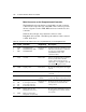
Table 22 shows the pin out for the male connector on the
Daughterboard controller. The Molex part number for this connector
is 8624-10-88-1141.
Table 22. Pin Out for the Male Connector (14-pin Dual Row) on the Daughterboard
Pin # Signal Definition Supplied By Description
1
2
3
CLK
CE
DIO
NOVRAM clock
NOVRAM chip enable
NOVRAM data
Daughterboard
controller
Signals used by the controller to store
and retrieve linearization coefficients
from the non-volatile RAM
(NOVRAM) located on the
touchscreen cable.
4 VCC +5 VDC
Host system The +5 volt supply input provided by
the host system. The controller
requires 70 mA (typical), 85 mA
(maximum), +5% regulation, and 100
mV maximum ripple and noise.
5, 6 GND Signal ground
Host system Provides the return path for the supply
current.
7 RST Reset (active low)
Host system An active low input that can reset the
controller.
8 DRV Shield drive
Daughterboard
controller
Provides a digitized sine-wave output
to drive the shield on the touchscreen.
9
10
11
12
UR
LR
UL
LL
Upper right touch wire
Lower right touch wire
Upper left touch wire
Lower left touch wire
Daughterboard
controller
Bi-directional AC signals that detect
the current used to determine the
touch position.
13
14
RXD
TXD
Data from host to the
Daughterboard (receive)
Data to host from the
Daughterboard (transmit)
— Provide serial communication between
the Daughterboard controller and the
host system.