
Specifications


Appendix C TouchPen Controllers 103
TouchPen Diagnostics
TouchPen controllers do not have an LED. You can, however, use
the Unit Type command to obtain status information on the controller
hardware.
Connectors and Cabling
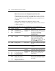
Figure 5 shows the layout of the TouchPen controller and connectors.
Table 20 describes the pins on each connector.
Table 20. Connectors and I/O Signals for the TouchPen Controller
Connector Description Pin Definitions
Pen OFNA R-06
(6-pin, 2 mm)
Connects to OFNA
PH-06 housing with
3222PS-2 pins
Pin 1: Ground (supplied to pen)
Pin 2: Pen Tip signal
Pin 3: Tip switch (data bit S0)
Pin 4: Side switch (data bit S1)
Pin 5: Switch 3 (data bit S2)
Pin 6: Shield drive (supplied to pen)
Sensor Molex 53015 series
(mates with Molex
51004 series)
Pin 1: Upper left (UL) corner
Pin 2: Upper right (UR) corner
Pin 3: Shield drive (supplied to sensor)
Pin 4: Lower right (LR) corner
Pin 5: Lower left (LL) corner
Pin 6: Ground (supplied to controller)
COM
and Power
Molex 53015 series
(with 7 pins)
Pin 1: +12 to +16 VDC power input
Pin 2: Ground (supplied to controller)
Pin 3: RXD (data input to controller)
Pin 4: TXD (data output from
controller)
The MicroTouch standard TouchPen
controller does not use Pin 5 – Pin 7.
The pin definitions are as follows:
Pin 5: -12 to -16 VDC power input
Pin 6: +5 VDC power input
Pin 7: HSYNC input