TM MicroScanner Pro ™ Users Manual (English) November 2001, Rev. 2, 9/03 © 2001-2003 Fluke Corporation. All rights reserved. All product names are trademarks of their respective companies.
LIMITED WARRANTY AND LIMITATION OF LIABILITY Each Fluke Networks product is warranted to be free from defects in material and workmanship under normal use and service. The warranty period is one year and begins on the date of purchase. Parts, accessories, product repairs and services are warranted for 90 days.
Table of Contents Title Introduction .................................................................................................................... Features .......................................................................................................................... MICROSCANNER PRO Kit Content ........................................................................................ Registration...............................................................................................
Length........................................................................................................................ Network Link Indicator ........................................................................................... Pair Length............................................................................................................. Coaxial Cabling...................................................................................................... Office Identifier..............
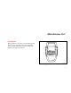
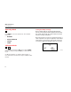
MicroScanner Pro™ Introduction MICROSCANNER PRO™ is an all-in-one network tester that you can use to verify twisted pair and coaxial cables, measure length and distance to faults via TDR, and identify active networks and hubs. MICROSCANNER PRO aue28f.eps Figure 1.
MicroScanner Pro Users Manual Features MICROSCANNER PRO Kit Content • Tests unshielded twisted pair (UTP), shielded twisted pair (SSTP) and coaxial cable Your MICROSCANNER PRO kit contains the following: • Pinpoints opens, shorts, crossed and split pairs • Measures cable length via TDR • Checks and verifies wiremap • Generates four different tracing tones to help identify users • Identifies active networking 10/100 hubs, switches, and PCs.
MicroScanner Pro™ Registration Registration Registering your product with Fluke Networks gives you access to valuable information on product updates, troubleshooting tips, and other support services. To register, go to the Fluke Networks website at www.flukenetworks.com/registration and fill out the online registration form. If you do not have Internet access, print the registration form that is on the CD included with the product.
MicroScanner Pro Users Manual Contacting Fluke Networks If you have technical questions, you may contact Fluke Networks’ Technical Support by phone, fax or e-mail. www.flukenetworks.com Before calling Technical Support, please have your Hardware and Software Version numbers available. To find out the version numbers, do the following: support@flukenetworks.com 1. Turn off the MICROSCANNER PRO. +1-425-446-4519 2.
MicroScanner Pro™ Battery Battery The Keypad MICROSCANNER PRO requires a 9 Volt Alkaline battery. The Battery icon is displayed on the screen when MICROSCANNER PRO detects a low battery condition. ON OFF When turned on, MICROSCANNER PRO flashes the LCD power-up test then resumes the test mode that was last executed. MICROSCANNER PRO turns off automatically when no cable is detected or when no key has been pressed for 10 minutes. Using MICROSCANNER PRO with a low battery may effect the test accuracy.
MicroScanner Pro Users Manual Operating Mode MODE Press MODE to select the desired test. The available modes are: • WIREMAP • OFFICE IDENTIFIER • LENGTH • TONER Setting the NVP percentage Once in Calibrate Mode, the default NVP (Nominal Velocity of Propagation) will be displayed followed by the overall cable length. The cable length is measured with the currently stored NVP. NVP is the measure of how fast a signal travels down a cable compared to the speed of light.
MicroScanner Pro™ Calibration Mode If you know a cable’s NVP, change the displayed numbers using the keys until the appropriate NVP is displayed. The cable length will automatically adjust to the new NVP. If you know a cable’s length, change the shown NVP using the keys until the appropriate length is displayed. The NVP can be adjusted in 1% increments, and the length changes accordingly. Cables used for calibration must be at least 50 feet (15 meters) long.
MicroScanner Pro Users Manual MICROSCANNER PRO Tests To conduct a Wiremap test: This section describes the tests that you can conduct with MICROSCANNER PRO. 1. Connect the cable to be tested to the MAIN jack (identified on the unit right above the modular 8 jack). 2. To display the Wiremap screen, press the MODE key until the word WIREMAP appears on the screen. Wiremap The Wiremap function tests twisted-pair cabling for proper wiring.
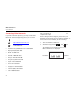
MicroScanner Pro™ MicroScanner Pro Tests Following are examples where MICROSCANNER PRO did not detect any faults. Token Ring unshielded shielded (2 pair, 4 wires) Full Wiremap with intact shield shown as Zero ‘0’ on the right (4 pair, 8 wires) aue05f.eps aue03f.eps 10BaseT Cable unshielded (2 pair, 4 wires) aue04f.
MicroScanner Pro Users Manual Below are examples of wiring faults. The FAULT indicator will be displayed and the numerical wire indicators will blink. Split Pair Reversed: Pair 3 – 6 aue08f.eps Note aue06f.eps Crossed: Pairs 4 – 5, 3 – 6 aue07f.eps 10 If a cable is wired correctly, pin-to-pin, but there is a split pair, Wiremap will display SPLIT PAIR. For example, a wire from the 1 - 2 pair could be twisted with a wire from the 3 - 6 pair.
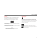
MicroScanner Pro™ MicroScanner Pro Tests If the wire does not go to the far end, the numerical indicator for the open will be left blank. The word Open will be displayed. Shorted pairs are indicated with a connecting bracket, and the word Short will be displayed. Short: Pair 1 – 2 Open: Pair 4 – 5 aue10f.eps When the wiring fault includes shorted or swapped non-pair pins (e.g. non-pair pins 1 - 3), the wiremap will display dashes for those numerical wire indicators. aue09f.
MicroScanner Pro Users Manual Patch Cable Wiremap Length The Wiremap function can also be used to verify patch cables. The Length function measures the full length of a twisted pair or coaxial cable. Twisted pair: If you are measuring standard pair length, MICROSCANNER PRO will determine whether the cable is open, shorted, or connected to a hub. 1. Simply plug the two ends of a cable into the two modular 8 jacks (MAIN and LOOP BACK) on MICROSCANNER PRO. 2.
MicroScanner Pro™ MicroScanner Pro Tests 2. To display the length screen, press the MODE key until the word LENGTH appears on the screen. The overall cable length will be shown. No Cable attached If the far end of a cable is connected to a hub, MICROSCANNER PRO will display HUB and the cable length. The cable is considered connected to a hub when the 3 - 6 pair is terminated and either pair 1 - 2 or 4 - 5 is terminated. Length to Hub aue11f.eps aue13f.eps 70 feet cable aue12f.
MicroScanner Pro Users Manual Some early model 100TX only network equipment does not generate link pulses and MICROSCANNER PRO will display HUB, the cable length and the word SIGNAL. Network Link Indicator The Network Link Indicator allows you to find and identify active network 10/100 hubs and confirm to which hub MICROSCANNER PRO is connected. It will blink the hub’s status indicator to assist locating a single channel in a busy wiring closet. 1.
MicroScanner Pro™ MicroScanner Pro Tests When MICROSCANNER PRO displays Hub and the cable length, press the MODE key to activate the blinking Hub light. MICROSCANNER PRO detects the kind of hub it is connected to: 10, 100, or 10/100 alternately will be displayed right after the word Hub. The number is followed by the letters F and/or H as an indication for the hub’s full or half duplex capabilities. Descriptions are as follows: aue16f.
MicroScanner Pro Users Manual MICROSCANNER PRO also Identifies workstations. 3. 1. Connect the cable to be tested to the MAIN jack (identified on the unit right above the modular 8 jack). 2. To display the length screen, press the MODE key until the word LENGTH appears on the screen. MICROSCANNER PRO displays the word PC followed by the length to the PC. aue17f.eps 16 When MICROSCANNER PRO displays PC and the cable length, press the MODE key to activate the blinking Hub light. aue18f.
MicroScanner Pro™ MicroScanner Pro Tests Pair Length Pair 1 - 2 Length If are displayed, you will be able to show detailed pair information for each standard conductor pair. key to display Pair 1 - 2 length. 1. Press the 2. key again to display the other pair Press the combinations. The pair length is not measured if the cable is too long, connected to a hub, or a wiremap adapter is used. aue19f.eps Pair 1 - 2 not measurable aue20f.
MicroScanner Pro Users Manual Coaxial Cabling 2. Connect the cable to be tested to the COAX adapter jack. 3. To display the length screen, press the MODE key until the word LENGTH appears on the screen. Note This feature is available when you use the COAX upgrade kit. MICROSCANNER PRO measures the full length of a 50 and/or 75Ω (Ohms) coaxial cable, e.g. RG-6 and identifies its termination state. 1. The overall cable length will be shown.
MicroScanner Pro™ MicroScanner Pro Tests If the coaxial cable is not terminated at the far end, the word Open will be displayed. If a shorted cable is detected, the words FAULT and Short will be displayed, and the length where the short has been found. Office Identifier The Office Identifier function allows you to find the termination of a twisted pair and/or a coax cable drop from a distribution panel.
MicroScanner Pro Users Manual 1. 2. Attach the coax adapter to the MAIN jack (identified on the unit right above the modular 8 jack). To display the Office Identifier screen, press the MODE key until the word OFFICE is displayed on the screen. 3. Insert the Office Identifier plugs into wall outlets in the offices you wish to locate. 4.
MicroScanner Pro™ Toner Toner Toner is a cable tracing function that assists in tracking cables hidden in walls, ceilings, floors, or patch panels by generating four distinct multi-tone signals that can be received by a cable tracer. To trace a cable, use any inductive probe capable of receiving a 1000 Hz signal, such as the Fluke Networks MicroProbe, IntelliTone Probe, or any equivalent tracing device to convert a signal on the cable into an audible tone.
MicroScanner Pro Users Manual Technical Specifications Dimensions: MICROSCANNER PRO: 13.97 cm x 8.25 cm x 2.54 cm (5.5" x 3.25" x 1") Wiremap Adapter: 7.62 cm x 3.18 cm x 2.11 cm (3" x 1.25" x .83") Office Identifier: 7.62 cm x 1.60 cm x 1.47 cm (3" x .63" x .58") Coax Adapter: 7.62 cm x 1.60 cm x 1.47 cm (3" x .63" x .58") Ground pin receptacle size: 2.03 mm (.08") 22 Weight: MICROSCANNER PRO: 171.54 g (.38 lbs) Wiremap Adapter/Office Identifier: 9.03 g (.
MicroScanner Pro™ Technical Specifications Environmental: Calibration: Operating Temperature: 0° to 50° C (32° to 122° F) User selectable NVP Storage Temperature: -10° to 55° C (14° to 131° F) NVP calculation based on known cable length Humidity: 10 % to 90 % non-condensing Minimum length: 15 meters (50 feet) Applications: Shielded and unshielded twisted pair cable, 75 or 50 ohm coaxial cable, 10 or 10/100 BASE-T Networks Test Interface: Main: Modular 8 connector for length, 10/100 link identificati
MicroScanner Pro Users Manual 24