MICROTEL CellStat TM Microtel CellStatTM Operating Manual 19 July 2008 Rev. C Proprietary Notice: This document and the subject matter hereto are the property of MICROTEL, Inc. and shall not be reproduced or copied or used for the purpose of manufacturing or sale of apparatus, except by written permission of MICROTEL. MICROTEL 11725 Sunbelt Court Suite C Baton Rouge, LA 70809 225-303-0436 Fax: 225-303-0568 www.microtel-inc.
MICROTEL CellStat TM Record of Changes Rev. A B C ii Date 12/28/06 3/1/07 8/13/07 7/19/08 Description of Changes Original Release Added descriptions of new wireless features Added description of Log-Stat™ Added description of new 2.
MICROTEL CellStat TM TABLE OF CONTENTS INTRODUCTION CHAPTER 1 - 3 DESCRIPTION OF THE CELLSTATTM DIALER Theory of Operation CHAPTER 2 - INSTALLATION Quick Start Procedure CHAPTER 3 - OPERATION 5 7 10 13 15 Configuration Basic System Information Configuring Fault Inputs Telephone Numbers Setting the Email Address 16 16 18 20 20 Operations Alarm Acknowledgment Checking System Status Using the Log-Stat™ Web-based Application Controlling the local output relay 21 21 22 22 25 CHAPTER 4 - MAINTEN
MICROTEL CellStat TM LIST OF ILLUSTRATIONS Figure 1: Figure 2: Figure 3. Figure 4: Figure 5: Figure 6: 2 Controls and Indicators................................................................................4 Power Supply Connection ...........................................................................10 External Cellular Antenna Connector…………………………………….. 11 I/O Terminal Connections ...........................................................................
MICROTEL CellStat TM INTRODUCTION hank you for choosing the Microtel CellStatTM Dialer to implement your remote alarm monitoring solution. You have chosen a product that is simple to set up and easy to use. CellStatTM has been designed and manufactured to operate with minimal operator intervention. T The Microtel CellStatTM features a single level, interactive command structure--there are no multi-level menu structures to navigate.
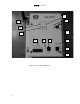
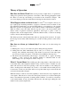
MICROTEL CellStat TM 11 2 12 10 9 1 8 6 7 5 3 4 Figure 1: Controls and Indicators 4
MICROTEL CellStat TM CHAPTER 1 - Description of the CellStatTM Dialer he CellStatTM is a small, rugged, and simple, but powerful, device which easily handles complex dialing or wireless notification and alarm monitoring. To accomplish these tasks, CellStatTM has an equally simple operator interface. Figure 1 illustrates the controls and indicators of the dialer, and the following paragraphs describe them.
MICROTEL CellStat TM (10) CELLULAR STATUS LED indicates cellular signal strength or call in-progress: BLINK (Rapid) = Cellular initialization / network registration in progress. 1 BLINK (Very brief) = Cellular signal strength unknown or undetectable. 1 BLINK (Long) = Weak cellular signal strength. 2-3 BLINK = Normal cellular signal strength. 3-5 BLINK = Strong cellular signal strength. ON STEADY = Cellular call in progress. The Cellular Status LED repeats its pattern after 5 seconds of OFF time.
MICROTEL CellStat TM Theory of Operation How Does the Dialer Work? This section provides a simple theory of operation by asking a few questions about typical use of the dialer. The following paragraphs assume the dialer is hooked up and running as described in the Installation chapter. The Operation chapter provides the details that are missing from the discussion below.
MICROTEL CellStat TM Will the Dialer Call Me Back? Maybe. The dialer has a snooze timer. When an alarm is acknowledged, the snooze timer is started, and alarm calls for all acknowledged faults are suspended. If a channel is still in alarm after the snooze period ends, then the dialer will begin a new alarm dialing sequence (starting with logging the event to the email address, then calling the first number on the telephone list).
MICROTEL CellStat TM If the user enters the correct code, access will be granted and the user may review or program the dialer’s configuration using the touch-tone commands described in this manual. If at any time during remote menu access the user does not enter a command within 30 seconds, the dialer will speak a disconnect warning and hang up.
MICROTEL CellStat TM CHAPTER 2 - Installation I nstallation of the CellStatTM involves several, simple steps. This chapter outlines the physical connections to the dialer. At the end of this chapter is a Quick Start procedure which summarizes the configuration procedure of the dialer. Step One - Connect the Power Supply Connect the supplied external transformer to the 12 VDC terminals as shown in Figure 2 below. Plug the transformer into a MicroMax Surge Suppressor (Recommended by Microtel). Figure 2.
MICROTEL CellStat TM Step Two - Telephone Connections (Optional) include the external phone line for call-outs and the optional local telephone connection for local programming and monitoring. If only the built-in cellular interface is to be used, then no telephone connections are necessary. CAUTION: This equipment cannot report an alarm when other equipment (telephone, answering system, computer modem, etc.) connected to the same phone line is in use. 1.
MICROTEL CellStat TM Step Four - Connect External Input/Output to the Dialer Each Fault input has a corresponding terminal (1 - 4), and there are two COM terminals. See Figure 4 below. The terminals are large enough to accept two 14 AWG wires, so if more than two faults are wired, the COM terminals must be shared. The fault sensing circuitry is transformer and optically isolated from the dialer circuitry, but all faults share the same COM.
MICROTEL CellStat TM Quick Start Procedure This procedure outlines the steps to get the CellStatTM dialer operating in a typical manner with a minimum of programming. 1. Plug the touch-tone telephone into the Dialer PHONE jack. 2. Connect external 12 VDC transformer to dialer power supply terminal block. NOTE: External power required in order to configure the dialer from a local phone. 3. Verify that the AC POWER/CHARGING LED illuminates (green). 4. Turn ON the dialer switch.
MICROTEL CellStat TM Individual Channel Alarm Messages: z Enter **c1 to record an alarm message for a specific I/O channel. (c = 1 to 4 for the I/O channel of interest). The dialer will respond “Ready”. z Speak your message clearly into the handset. z The dialer will speak back the message after the 6-second recording interval z Repeat procedure for the next I/O channel and message. 9. Verify Configuration Data is saved in the Dialer. Enter *00 and listen to the spoken status report.
MICROTEL CellStat TM CHAPTER 3 - Operation T his chapter, divided into Configuration and Operation sections, will explain how to configure the CellStatTM to react to I/O events and how an operator can make the dialer respond to remote commands. The Microtel CellStatTM features a single level, interactive command structure--there are no multi-level menu structures to navigate.
MICROTEL CellStat TM Configuration The configuration commands described in this section modify basic dialer operation and store information about the dialer’s operational behavior in nonvolatile memory. You should only have to configure your dialer once -- all changes are saved permanently, even if AC and battery power are removed from your dialer. This section consists of the following subsections: z z z z Basic System Information - Set/Query various system values.
MICROTEL CellStat “set system id ” TM Configure a custom SMS system text id Example- Command: “set system id Richfield lift 1” NOTE: You must enter the “set system id ” portion as shown. That is, there must be a single space between each word and after “id”. NOTE: The custom system text id can be up to 16 characters long. Example- Alarm event: “Richfield lift 1 Channels in Alarm:1,” NOTE: Display formatting on your mobile phone may be slightly different.
MICROTEL CellStat Example- Command: Response: TM **0412 The snooze delay is one two hours. z Firmware Version *05 Report Firmware Version Response will play back all resident vocabulary, then speak “Cell Stat version number is two point one zero”, where “ two point one zero” is the current firmware version (e.g. 2.10). z Control Local Output Manual control of local output contacts.
MICROTEL CellStat TM A new channel name can be recorded with the '**c1' command. Once the command is typed record your voice message after the dialer prompts you “Ready”. A maximum of 6 seconds of recording time is allowed for each fault input message. z I/O Channel Fault Delay When channel c changes state, this timer delays an alarm until the channel has been in the alarm state for (SS) seconds. This parameter will filter out noisy, or temporary, state changes from placing undesired nuisance alarm calls.
MICROTEL CellStat TM Example- Command: Response: **141 Channel one alarm clear status is enabled. Example- Command: Response: **440 Channel four alarm clear status is disabled. Telephone Numbers As described in the theory of operation in Chapter 1, CellStatTM can store up to eight (8) phone numbers in the System Telephone Directory. This section explains how to program the dialer’s telephone numbers and shows how to customize the numbers for certain call-out situations.
MICROTEL CellStat Response: TM None NOTE: CellStatTM’s built-in cellular phone number is printed on a label on the left side of the enclosure, near the antenna. NOTE: Do not type the “” marks. NOTE: You must enter the “set email ” portion as shown. That is, there must be a single space after “set” and after “email”. NOTE: The email address can be up to 50 characters long. Example- Command: Response: “Email” “joe.smith@yahoo.
MICROTEL CellStat TM Checking System Status CellStatTM allows easy checking of system status and capability. Spoken reports of your entire remote-monitored system can easily be generated, or SMS text message status reports can be retrieved via the dialer’s built-in cellular capability. A spoken system status report can be received from the dialer by entering the following command from a touch-tone telephone either locally, or remotely after answering or calling the dialer.
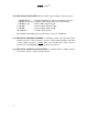
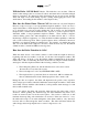
MICROTEL CellStat TM CellStat™ can be configured to log all alarm events wirelessly to Microtel’s optional web-based application, Log-Stat™. Upon a new alarm detection, CellStatTM can wirelessly transmit an event log to Log-Stat™ via its built-in cellular capability before it begins calling the phone numbers on its list. This capability provides the benefit of an electronic record of each and every alarm event that occurs, accessible from any web browser.
MICROTEL CellStat TM Figure 5: Log-Stat™ screen shot 24
MICROTEL CellStat TM Controlling the local output relay CellStatTM has a set of output contacts that may be controlled from a touch-tone phone. These contacts may be used to turn ON or OFF external equipment, or as a signal input to another device. Simply enter the following command during a phone call to or from the dialer, via either the phone or cellular connection. NOTE: de-energized state is open.
MICROTEL CellStat TM CHAPTER 4 - Maintenance/Troubleshooting he CellStatTM Dialer is built to require minimal maintenance. Only the system battery requires your attention from time to time for your dialer to continue performing with no problems. T INTERNAL RECHARGEABLE BATTERY: A battery in typical standby use will last approximately 2 to 4 years. Battery life is mostly dependent upon the number of power outages sustained, the age of the battery, and temperature.
MICROTEL CellStat TM (e.g. US Bank), or from the carrier’s web site. You will need to know the phone number and the carrier that is printed on the label. In addition to minutes being depleted from your dialer’s prepaid cellular account due to the dialer’s usage of the cellular account, minutes also expire after fixed time periods. The dialer is commissioned with $100 of prepaid cellular minutes at the factory; this initial account expires after one year.
MICROTEL CellStat TM Troubleshooting Guide Symptom: Cause: Cause: Cause: Cause Symptom: Cause: Cause: Cause: Cause: Cause: Cause: Unable to program with local telephone. External 12 VDC power required. (Green AC power/charging LED must be on) Incorrect command format (all commands begin with * or **). To clear out the message buffer at any time, press the ‘#’ key. Touch-tone phone must be used (listen for tones when keys are pressed).
MICROTEL CellStat TM cover and turning clockwise to increase loudness, counter-clockwise to decrease. Symptom: Cause: Cause: Cause: Cause: Cause: Symptom: Cause: Cause: Cause: Cause: No alert is sent to the email address. Check if an email address is configured in the dialer by text-messaging “email” to the dialer’s cellular phone number. Add an email address by text-messaging “set email youremail@youremailaddress” to the dialer’s cellular number. Cellular prepaid balance is too low.
MICROTEL CellStat TM CHAPTER 5 - Advanced Topics T his chapter details more advanced topics concerning the setup, configuration, and operation of the CellStatTM dialer. Advanced Configuration Options z Call Progress Decoding Features CellStatTM has very powerful call progress decoding features which allow great flexibility in making phone calls to pagers, answering machines, voice mail, or regular or cellular telephones.
MICROTEL CellStat Example 1- Command TM Program phone number 3 | Dial a pager system at 5551212 | | Suppress voice message for numeric pager and wait for answer at this point | | | Pause 6 seconds, | | | | Dial ‘123’ | | | | | Terminate | | | | | | **63 5551212 *3 *2*2 *2 123 ** Response: Telephone number three is five five five one two one two STAR three STAR two STAR two STAR two one two three.
MICROTEL CellStat Example 4- Command Response: TM Program phone number 8 | Pulse dial the following digits | | | **68 | | | *1 Dial phone number 5551212 | Terminate | | 5551212 ** Telephone number eight is STAR one five five five one two one two z Reduced power operation CellStatTM’s already low power consumption can be reduced 33% for installations providing minimal power, such as solar panels.
MICROTEL CellStat **055 TM Toggle cellular prepaid plan Example- Command: Response: Effect: Example- Command: Response: Effect: Example- Command: Response: Effect: **055 Cellular balance status is disabled and cellular channel is zero. Turns OFF the cellular prepaid algorithm and selects AT&T/Cingular (cellular channel zero) as the carrier. **055 Cellular balance status is disabled and cellular channel is one.
MICROTEL CellStat TM APPENDICES APPENDIX A: Technical Specifications A.1 Communications 34 Phone Interface: ACTA ID: US: 7AAAD00BDS65616 For connection to PSTN Ringer Equivalence Number: 0.0B Cellular Interface: Enabled with installation of a GSM SIM card and External antenna (usually done at factory); frontpanel cellular status indication and volume control.
MICROTEL CellStat TM Wireless logging of alarm events to Log-Stat™ web-based application; Tone or Pulse Dialing via the PSTN; Special Sequences for Selection of Pulse/Tone, Pause, Pagers, Auto-Acknowledging Alarms; Cellular voice callout, cellular SMS Text Message. A.2 Call Progress Detection Dial Tone Detect Busy Detect Ring Back/No Answer Detection Answer Delay: 1-99 Rings (Call Back Acknowledge) via PSTN 1 – 3 rings when using the built-in cellular interface. Electrical Input Power: 1.
MICROTEL CellStat TM (7.7" wide 8.8" high x 4" deep) Suitable for Wall or Panel Mounting Battery Mounted Separately Nema 4 Fiberglass Case with Hard Cover (12” Wide, 15.5” High, 6.6” Deep) Nema 12 Fiberglass Case with Hard Cover Nema 12 Fiberglass Case with Clear Cover (9” Wide, 10.5”High, 6.5” Deep) Weight: Panel Mount Unit Nema 12 case: Full system: 4 lbs 6 lbs 10 lbs A.6 Speech Type: Nonvolatile, with Automatic Gain Control of userrecorded messages.
MICROTEL CellStat Cellular Fault Detection: TM Alert generated when cellular prepaid balance < $5 A.8 Temperature Measurement Type: Accuracy: Reporting Resolution: Onboard, internal to the enclosure, temperature IC +/- 5 degrees Fahrenheit 1 degree Fahrenheit, current and historic low, high A.
MICROTEL CellStat APPENDIX B: TM Glossary of Dialer Terminology Acknowledge Stops the dialer from placing additional calls concerning an alarm condition. Acknowledgment can be made by entering the '*' during alarm playback, with call-back acknowledge, or by an auto acknowledge phone escape sequence (*4) embedded within the telephone number. Alarm condition An event detected by the dialer usually causing a phone call.
MICROTEL CellStat APPENDIX C: TM FCC Requirements This equipment complies with Part 68 of the FCC rules and the requirements adopted by the ACTA. On the side of the CellStatTM metal case is a label that contains, among other information, a product identifier in the format US:AAAEQ##TXXXX. If requested, this information must be provided to the telephone company.
MICROTEL CellStat TM APPENDIX D: CellStatTM Command Summary *00 *01 *02 *03 *04 *05 *06 *c1 *c2 *c3 *c4 **01~ **02nn **03nn **04HH **060/1/2 **c1~ **c2SS **c31/0 **c41/0 *6n **6np** Report system status Voice system name (10 seconds) Answer Delay (00 – 99 rings) Access Code (00 = Disabled) Snooze Delay (HH = 00 – 99 Hours) Recites vocab & firmware version Control local output Fault Fault Fault Fault c c c c voice name delay (00 – 99 Seconds) alarm configuration Return-To-Normal config Telephone n (n
MICROTEL CellStat APPENDIX E: TM Mechanical Dimensions 7.63 6.75 0.375 1.06 0.25 MICROTEL CELLULAR STATUS VOLUME ON + _ ALARM STATUS OFF CH1 CH2 CH3 CH4 12VDC 5.56 8.63 AC POWER/ CHARGING OUTPUT INPUTS 1 COM 2 3 RING/ ACTIVE OFF HOOK 4 COM PHONE LINE .