
OPERATIONS MANUAL Wireless Ethernet Systems


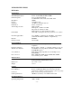
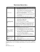

WEM SPECIFICATIONS (cont’d)
Power Injection Module
MECHANICAL
Physical Plastic housing, not weatherproof
Dimensions 2.6” x 2.6” x 1.1”
Weight 2.5 oz
Interface 2 – RJ45 connectors
POWER
Power Requirements 12 VDC 500 mA (wall transformer supplied)
Power-over-Ethernet (PoE) PoE “mid-span” compliant (pins 4,5 positive – pins 7,8
ground)
Indicator LED - red
Connectors DC Jack 2.5 mm x 5.5 mm center positive, 2 – RJ45
ENVIRONMENTAL
Humidity 95% non-condensing
Operating Temperature -20F to +150F
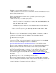
System Ranges
POINT-TO-POINT SYSTEMS
_______
Up to 2500 Feet Integral directional patch antennas on both WEMs
Up to 2 Miles Integral directional 6 x 6 13-dBi patch antennas on both
Up to 12 Miles Integral directional 6 x 6 13-dBi patch antenna on the Host
with integral directional patch antenna in 25 dBi dish
antenna on the Client
Up to 30 Miles Integral directional patch antennas on both WEMs mounted
in 25 dBi dish antennas
Distance specifications assume an optimal environment (see pg ii for details)
MULTI-CONNECT SYSTEMS
Up to 500 Feet Integral omni-directional patch antennas on both the Host
AP WEM & Client SU WEM
Up to 1300 Feet Integral omni-directional patch antenna on the Host AP
WEM & integral directional patch antenna(s) on the Client
SU WEM(s)
Up to 2500 Feet Integral directional patch antenna on the Host AP WEM &
Client SU WEM(s)
Up to 1 Mile Integral directional patch antenna on the Host AP WEM &
integral directional 6 x 6 13-dBi patch antenna(s) on the
Client SU WEM(s)
Up to 6 Miles Integral directional patch antenna on the Host AP WEM &
Client SU WEM(s) – Client SU WEM(s) mounted in 25 dBi
dish antenna(s)
Distance specifications assume an optimal environment (see pg ii for details)
*For product improvement, design and specifications are subject to change without notice.
- 20 -