
OPERATIONS MANUAL Wireless Ethernet Systems
WEM INSTALLATION & OPERATION (cont’d)
E. CONNECT HOST/CLIENT
Connect the cable to the Host/Client. Slide the cable jacket up to the base of the connector.
Slide the weatherproof connector over the cable jacket and screw it into the Host/Client and
tighten. Tighten the clamping nut until the CAT5 cable is sealed in the connector. Check the
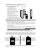
antenna positioning and make sure the Power and Link Activity LEDs are on. The Link Activity
indicator, amber LED, will only illuminate if an Ethernet source device is connected and
powered up, and the red LED will verify power is being sent over the Ethernet cable. See
drawing B-2 (page 7).
F. ESTABLISH LINK
Follow above steps, A through E, for both ends of the link to be established. After both ends
have been installed and powered up, the green Signal Level LED will illuminate. A solid green
LED indicates the radios are communicating at a maximum throughput standard rate of up to 20
Mbps. If the green LED is flashing, the units are communicating at a level less than max signal
strength. If this occueD iLEDi97e csEignsds of