
OPERATIONS MANUAL Wireless Ethernet Systems


WES CONNECTION DIAGRAMS
The following wiring schemes represent the configurations that have been tested and verified by MicroTek
Electronics based on typical Ethernet wiring solutions. Other wiring configurations could be possible based on
the application. A bench test is recommended to verify the designs below.
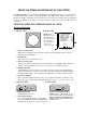
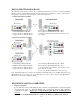
A. POINT-TO-POINT SYSTEM
ML ENC shown ML DEC shown
B. MULTI-CONNECT SYSTEM
1. Client Wireless Ethernet Module
2. Host Wireless Ethernet Module
3. Cat5 Connection to Ethernet Device
4. Cat5 Connection to Ethernet Device
ystem
5. Power Injection Module Ethernet Out to Client
6. Power Injection Module Ethernet Out to Host
7. Antenna separation of less than max system range, clear
line-of-sight
ML ENC shown
ML DEC shown
ML DEC shown
ML ENC shown
5. Power Injection Module Ethernet Out to Client
6. Power Injection Module Ethernet Out to Host
7. Antenna separation by 90 Degrees; less than max s
range, clear line-of-sight.
1. Client Wireless Ethernet Module
2. MP Host Wireless Ethernet Module
3. Cat5 Connection to Ethernet Device
4. Cat5 Connection to Ethernet Device
8. 4-(or more)-RJ-45-Port Switch
(Not a MicroTek product)
Note: The Ethernet/IP device connects to the “Ethernet In” RJ45 Ethernet port on the PIM. Depending on the
Ethernet/IP device you are using, a crossover cable may be needed. No cable connection from Host/Client to
Ethernet device should exceed 300 feet (100m).
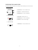
WEM INSTALLATION & OPERATION
A. SELECT CHANNEL
Locate and remove the ½ inch diameter plug at the side of the Host/Client. Select the channel
the system will operate on. Each Host/Client pair or group must share the same channel to
communicate properly. Replace the ½ inch diameter plug after the channel has been
selected.
Note: Power to the Host/Client must be cycled for the unit to recognize a new channel.
- 6 -